
Page 557 - eProceeding for IRSTC2017 and RESPeX2017
P. 557
PID controller is suitable for fixed parameters processes that could be mathematically modeled using linear first or second order
systems. However, an accurate model of a real industrial process is difficult to obtain, since the process itself may have complex
characteristics such as nonlinearity, high order, delay-time, dead-time, etc. That cannot be easily modeled using a simple linear
system [5]. In addition, the process may be affected by parameter variations due to temperature, ageing components, noise, and load
disturbance. For these complex processes, tuning laws based on these inaccurate models are no longer adequate to attain the
controller gains properly. PID (Proportional, Integral and Derivative) controller has been the basis in simple linear control systems.
It is a well-known and well–established technique for various industrial control applications. This is mainly due to its simple design,
straight forward parameters tuning and robust performance. As actuators, DC servomotors are extensively used in many automatic
controls, including drive for robotic manipulators, machine tools, rolling machines, photocopy machines etc. PID controllers are
usually used to control these servomotors. Position controls utilizing PID can be seen in [6],[7],[8],[9],[10]. To design an effective
PID controller, three gain parameters, namely, proportional gain, integral gain and derivative gain need to be specified accordingly.
The conventional approach to determine the PID parameters is to study the mathematical model of the process and try to come up
with a simple tuning law that provides a fixed set of gain parameters. One example of such approach is the Ziegler-Nichols method
[11]. This paper uses PID controller and introduces the Single Acting Pulley Actuator Continuously Variable Transmission (SAPA
CVT) ratio control with one DC motors as its actuators. This actuator works only during transmission ratio changes, hence
shortening actuator’s operation time and reducing energy loss.
2. Background of CVT
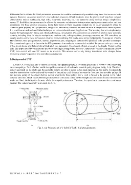
A basic CVT works just like a variator. It consists of a primary pulley, a secondary pulley and a rubber V-belt connecting
these two pulleys. Each of driver and driven pulley consists of a fixed and a movable pulley is given in fig. 1.(a). The fixed
pulleys are fixed on the shafts and the movable pulleys are able to move in the axial direction on the shafts. Continuously
variable transmission can be achieved by control of the pulley axial distance between the fixed and the movable pulleys. If
the movable pulley of the driver shaft is moved towards the fixed pulley, the V -belt is forced to be pushed in the radial
outward direction, which causes the belt pitch diameter to increase. Since the belt length and the center distance between the
shafts are fixed, the belt pitch diameter of the driven pulley decreases. Therefore, the speed ratio decreases in a continuous
manner. The variator geometry is given in fig. 1.(b).
(a) (b)
Fig. 1. (a) Principle of a V-belt CVT; (b) Variator geometry.
555 | V O L 1 1 - I R S T C 2 0 1 7 & R E S P E X 2 0 1 7