
Page 11 - DYNATECH
P. 11
INSTRUCTIONS: VEGA Cod: DYN 35.1.12
Date: 30/01/2017 Revision: 12
4.8 HARDENED GROOVE
It is possible to order the governor with a hardened groove. The following data is provided to assess whether or not
ordering the governor with this option is required.
Non-hardened groove: 500000 cycles
Hardened groove: 1500000 cycles
Note: This data is the result of tests performed on Dynatech premises and are for illustrative purposes only. The
wear depends on the type of installation, traffic, tension on the governor rope, speed, etc.
The client must decide whether or not to select this option depending on the type of installation
4.9 VEGA GOVERNOR’S COVER
As an option, a cover may be installed for the governor in order to avoid bumps, entanglement or other damage
caused by the rotation of the governor’s mobile parts.
This is a cover reaching the main part of the governor. It is easy to assemble.
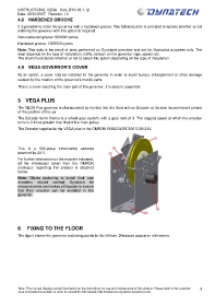
5 VEGA PLUS
The VEGA Plus governor is characterised by the fact that it is fitted with an Encoder at the rear for permanent control
of the position of the car
The Encoder turns thanks to a wheel gear system, with a gear ratio of 3. The angular speed at which the encoder
turns is 3 times greater than that of the main pulley.
The Encoder supplied in the VEGA plus is the OMRON E6B2CWZ6C500 0.5M 24V.
This is a 500-pulse incremental encoder
powered by 24 V.
For further information on the encoder indicated,
all the information taken from the OMRON
catalogue regarding this product is attached
below.
Note: Clients preferring to install their own
encoders should contact Dynatech for
measurements and makes of Encoder to ensure
that their encoder can be installed in the
governor.
6 FIXING TO THE FLOOR
The figure shows the governor anchoring points to the lift floor. Distances appear in millimetres.
Note: This manual displays partial information on the instructions for use and maintenance of this product. Please refer to the customer 9
area in Dynatech’s website in order to consult the full manual; http://customers.dynatech-elevation.com/