
Page 9 - DYNATECH
P. 9
INSTRUCTIONS: VEGA Cod: DYN 35.1.12
Date: 30/01/2017 Revision: 12
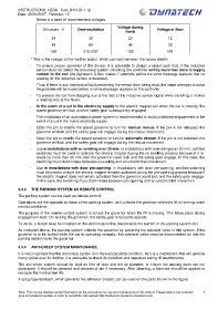
Below is a table of recommended voltages.
Voltage during
All values - V Over-excitation Voltage at floor
travel
24 30 20 12
48 60 40 30
190 215-205* 150 104
* This is the voltage at the rectifier output, which can vary between the values shown.
- To ensure proper operation of the device, it is advisable to design a circuit such that, if the inductive
sensor does not detect the anti-creep system unlocking, the controller will try more than once to supply
current to the coil (the Dynatech D-Box makes 7 attempts before the error message appears that no
reading for the inductive sensor is detected).
Thus, if there is any mechanical fault preventing the sensor from being read, the same attempts to solve
the problem will be made before an error message appears on the controller.
- To prevent the car from stopping due to the loss of the inductive sensor signal while travelling, it makes
a reading only at the floors.
- In the event of a cut in the electricity supply to the electric magnet coil when the car is moving, the
speed governor will lock and the safety gear subsequently engaged.
The installation of an autonomous power system is recommended to avoid undesired engagement in the
event of a cut in the mains electricity supply.
- Open the pin to enable the speed governor to turn for manual rescue. If the pin is not released, the
governor will lock and the safety gear will engage during the rescue movement.
- Open the pin to enable the speed governor to turn for automatic rescue. If the pin is not released, the
governor will lock and the safety gear will engage during the rescue movement.
- Use in installations with re-levelling over 20 mm: in installations with re-levelling over 20 mm, certified
switching must be used to activate the electric magnet during the re-levelling process because if it re-
levels by more than 20 mm then the governor could lock and the safety gear engage. In this case, the
switching must discriminate between re-levelling and an uncontrolled movement.
- Use in installations with door pre-opening: in installations with door pre-opening, certified switching
must be used to ensure the electric magnet remains activated during the pre-opening process because if
the electric magnet does not remain activated then the governor could lock and the safety gear engage.
In this case, the switching must discriminate between pre-opening and an uncontrolled movement.
4.4.3 THE PARKING SYSTEM AS REMOTE CONTROL
The parking system can be used as remote control.
Operations are the opposite to those of the parking system, as it unlocks the governor when the lift is running under
normal conditions.
The purpose of the remote control system is to lock the governor when the lift is moving. This takes place during
engagement tests. On locking the governor, the safety gear is forced to operate.
To do so, a button must be installed on the control panel that disconnects the current to the parking system coil.
As indicated above, the parking system unlocks the governor by powering the solenoid valve in this system. If the
governor is to be locked while the car is operating normally, this solenoid valve must be disconnected so that the
parking system locks the governor.
4.4.4 ANTI-CREEP SYSTEM MAINTENANCE
It is very important that the anti-creep system is in the best possible condition. As it is a mechanism that will perform
many cycles over its lifetime, it is advisable to check its condition and operation during lift maintenance.
The anti-creep system should be kept as free of dust and dirt as possible, to ensure the moving parts are not
obstructed. It should be checked and cleaned of dirt if necessary. After cleaning, a lubricant should be applied to
increase the mechanism life.
A spray type lubricant, which prevents the adhesion of dust, can be used on the parts shown in the figure.
Note: This manual displays partial information on the instructions for use and maintenance of this product. Please refer to the customer 7
area in Dynatech’s website in order to consult the full manual; http://customers.dynatech-elevation.com/