
Page 4 - DYNATECH
P. 4
INSTRUCTIONS: VEGA Cod: DYN 35.1.12
Date: 30/01/2017 Revision: 12
1 GENERAL INSTRUCTIONS
The DYNATECH VEGA overspeed governor is designed to cut off the current of the security series line in the event
of car overspeed, bringing the lift to a standstill when necessary.
The VEGA overspeed governor covers a wide range of speeds and can be used with instant and progressive safety
gears.
It is strictly forbidden:
a) To modify or replace the overspeed governor adjustment spring.
b) Use an overspeed governor in a lift for which it is not intended, or whose features do not correspond to those
marked on the lift (e.g. nominal speed or rope type).
c) To adjust any component of the overspeed governor, except for those parts specified in the manual.
DYNATECH DYNAMICS & TECHNOLOGY, SL will not be liable for any damage caused by failure to observe any of
these general conditions.
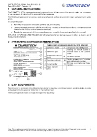
2 OVERSPEED GOVERNOR IDENTIFICATION
OVERSPEED GOVERNOR IDENTIFICATION STICKER
1 Governor model 7 QR product traceability code
Marking for market access to
2 Governor type 8 member states of the Customs
Union
Performance speed
3 9 Dynatech address
(m/s)
Quality assurance CE marking
4 Rated speed (m/s) 10
and notified body number
EU type examination certificate
5 Serial number 11
number
Rope diameter
6
(mm)
3 MAIN COMPONENTS
Each governor is composed of the following main elements: a pulley, a centrifugal system, a locking device, a casing
and a plate to link the governor to the floor in the machine room.
The following picture shows an image of the governor assembly:
Note: This manual displays partial information on the instructions for use and maintenance of this product. Please refer to the customer 2
area in Dynatech’s website in order to consult the full manual; http://customers.dynatech-elevation.com/