
Page 5 - DYNATECH
P. 5
INSTRUCTIONS: VEGA Cod: DYN 35.1.12
Date: 30/01/2017 Revision: 12
Where:
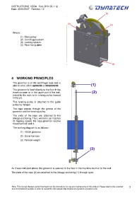
(1) Main pulley.
(2) Centrifugal system.
(3) Locking system.
(4) Floor fixing plate
4 WORKING PRINCIPLES
The governor is of the centrifugal type and is
able to work either upwards or downwards.
The governor is fixed directly to the floor in the
machine room or in the upper part of the well,
joined by the rope to its tensing pulley located
in the pit.
This tensing pulley is attached to the guide
pulley by flanges.
The rope passes through the groove of the
governor and the tensing pulley.
The ends of the rope are attached to the
linkage anchoring. Thus, when the car reaches
its tripping speed, the rope-governor relative
movement will lock it.
The working diagram is as follows:
(1) VEGA governor
(2) Governor rope
(3) Tension weight
As it was indicated above, the governor is secured to the floor in the machine room or to the well.
The ends of the rope (2) are attached to the linkage anchoring (1) through eyes.
Note: This manual displays partial information on the instructions for use and maintenance of this product. Please refer to the customer 3
area in Dynatech’s website in order to consult the full manual; http://customers.dynatech-elevation.com/