
Page 2576 - Foton Workshop Manual - Sauvana
P. 2576
62-524 DIAGNOSIS-ENGINE CONTROL SYSTEM
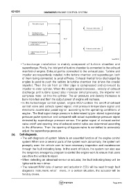
Revolution signal
Pressure relief valve
Intake pressure
temperature signal
ECU
Electronic accelerator
pedal signal
Exhaust control valve
Supercharge pressure
signal
fuwx62032
• Turbocharge installation is mainly composed of turbine chamber and
supercharger. Firstly, the inlet port of turbine chamber is connected to the exhaust
manifold of engine. Exhaust port is connected to the exhaust pipe. Turbine and
impeller are respectively installed in the turbine chamber and supercharger, both
of them being connected to axial stiffness. Exhaust inertial force discharged by
engine is used to push the turbine in turbine chamber that drives the coaxial
impeller. Then the air from air filter pipe is compressed and conveyed by
impeller to enter cylinder. When the engine speed increases , velocity of exhaust
discharge and turbine speed also increase simultaneously, the impeller will
compress more air into the cylinder. The air pressure and density increases to
burn more fuel and then the output power of engine will increase.
• In the turbocharger control system, engine ECU controls the on/off of exhaust
control valve and collects speed signal, inlet pressure temperature signal and
electronic accelerator pedal signal according to the operating conditions of
engine . The final supercharge pressure is determined by pre- stored supercharge
pressure pulse spectrum and compared with actual supercharge pressure signal
detected by supercharge pressure sensor. The pulse signal of exhaust control
valve on/off and opening time of exhaust control valve are determined according
to the difference. Then the opening of bypass-valve is controlled to accurately
adjust the supercharge pressure.
(n). Self-diagnosis.
• The self-diagnosis of system failure is an essential function of the engine control
system When one or several parts of the system work abnormally, the system will
promptly warn the vehicle user to have necessary inspection and maintenance
through the fault indicating lamp. In the event of failure, the system can also use
the temporary emergency program to control the engine work to ensure that users
can drive the vehicle to repair.
• When detecting an abnormal sensor or actuator, the fault indicating lamp will be
lightened to warn driver.
• The relevant RAM data of sensor and actuator in ECU will be read through fault
diagnosis instrument. what’ more, in a certain situation, the actuator will be
forcibly driven.
Page 2576