
Page 35 - Foton Workshop Manual - Tunland (AT)
P. 35
INTRODUCTION - HOW TO TROUBLESHOOT 01-29
2 . Check for Broken Circuit 01
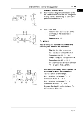
(a) See the circuit diagram as illustrated at the
left. Perform conduction test and voltage test
in Step 2 and 3 respectively, to identify the
position of broken circuit.
(b) Conduction Test
• Disconnect the connectors A and C
and measure the resistance in
between.
Resistance: < 2Ω
NOTICE
Slightly swing the harness horizontally and
vertically, and measure the resistance.
Take this circuit for an example.
If the resistance between Pin 1 of
Connectors A and C: ≥ 1 MΩ
And the resistance between Pin 2 of
Connectors A and C: < 2 MΩ
It means the circuit is broken between
Pin 1 of Connectors A and C.
• Disconnect Connector B and measure the
resistance between the connectors.
Take this circuit for an example.
And the resistance between Pin 1 of
Connectors A and B1: < 2 Ω
And the resistance between Pin 1 of
Connectors B2 and C: ≥ 1 MΩ
It means the circuit is broken between Pin 1
of Connectors B2 and C.
Page 35