
Page 512 - Foton Workshop Manual - Tunland (AT)
P. 512
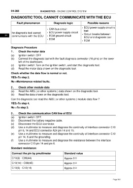
04-366                     DIAGNOSTICS - ENGINE CONTROL SYSTEM

           DIAGNOSTIC TOOL CANNOT COMMUNICATE WITH THE ECU


                 Fault phenomenon                  Diagnosis logic                Possible reasons
                                                                            • ECU power supply circuit is
                                            • CAN bus circuit
                                                                              bad
            he diagnostic tool cannot       • ECU power supply circuit
      04     communicate with the ECU       • ECM ground circuit            • Circuit breaks between
                                                                              ECU and diagnosis tool
                                            • ECM
                                                                            • ECM

           Diagnosis Procedure

           1 .    Check the motor data
           (a)    Ignition switch: OFF
           (b)    Connect the diagnosis tool with the fault diagnosis connector (16 pins) on the lower
                  left of the dashboard.
           (c)    Ignition switch: Turn on the ignition switch, and start the diagnostic tool.
           (d)    Read the motor data shown on the diagnostic tool.
           Check whether the data flow is normal or not.

           YES>To step 2.
           No >Maintenance related faults.

           2 .    Check other module data

           (a)    Read the ABS ( or other systems ) data shown on the diagnostic tool.
           (b)    Read the data shown on the diagnostic tool.

           Can the diagnostic tool read the ABS ( or other systems ) module data flow ?
           YES>To step 4.

           No >To step 3.

           3 .    Check the communication CAN line of ECU
           (a)    Ignition switch: OFF.
           (b)    Disconnect the battery negative cable.
           (c)    Disconnect the ECU connector.
           (d)    Use a multimeter to measure and diagnose the continuity of interface connector C10
                  pin 6, 14 and ECU connector A24 pin 14 and 15.
           (e)    Use a multimeter to measure and diagnose the continuity of interface connector C10
                  pin 14, 6 and the grounding.
           (f)    Use a multimeter to measure and diagnose the resistance between the interface
                  connector C10 pin 14 and pin 6.

           Standard resistance:

            Connect the pin by pmultimeter                  Standard value

            C10(6) - C99(44)                                Approx 0Ω
            C10(14) - C99(45)                               Approx 0Ω

            C10(6) - C10(14)                                Approx 0Ω


                                                                                                         Page 512