
Page 2340 - Workshop Manual - Tunland (2017)
P. 2340
71-140 WIRING - SYSTEM CIRCUIT DIAGRAM
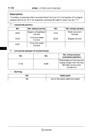
Description:
The battery is powered when the current flows from fuse F2 in the fuse box of the engine
compartment to pin 16 of the diagnostic connector through the body fuse box F12.
: component position
NO. Ref. wiring harness NO. Ref. wiring harness
Engine compartment Front instrument
A020 C041
harness harness
Front instrument
C005 E006 Engine harness
harness
Front instrument
C037
harness
71
: connectors between wiring harnesses
Ref. wiring harness
NO. NO.
(connector position)
Front instrument harness and
engine compartment harness
C105 A306
(left side of instrument
crossbeam)
: Earthing
NO. Earth point
B2 Left of the combination instrument