Page 36 - Workshop Manual - Tunland (2017)
P. 36

01-30                      INTRODUCTION - HOW TO TROUBLESHOOT
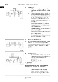
      01                                              (c)    Voltage Test
                                                             •     When the circuit is energized, check
                                                                   for broken circuit by means of voltage
                                                                   test.
                                                             •     Take the circuit as an example. All the
                                                                   connectors are connected. Measure
                                                                   the voltage between Pin 1 of Connector
                                                                   A, Pin 1 of Connector B, Pin 1 of
                                                                   Connector C at the 5V output of the
                                                                   control module and the grounding in
                                                                   sequence.
                                                                   If the following results are achieved:
                                                                   Voltage between Pin 1 of Connector A
                                                                   and grounding: 5V

                                                                   Voltage between Pin 1 of Connector B
                                                                   and grounding: 5V
                                                                   Voltage between Pin 1 of Connector C
                                                                   and grounding: 0 V
                                                                   It means the circuit is broken between
                                                                   Pin 1 of Connectors B and C.


                                                      3 .    Check for Short Circuit

                                                      (a)    As illustrated at the left, there is short circuit
                                                             between the harness and the grounding.
                                                             Perform conduction test between it and the
                                                             grounding in Step 2, to identify the short
                                                             position.


                                                      (b)    Conduction Test
                                                             •     Disconnect Connectors A and B and
                                                                   measure the resistance between Pins
                                                                   1 & 2 of Connector A and the
                                                                   grounding.
                                                                   Resistance: ≥ 1 MΩ

                                                           CAUTION

                                                      Slightly swing the harness horizontally and
                                                      vertically, and measure the resistance.

                                                                   Take this circuit for an example.
                                                                   If the resistance between Pin 1 of
                                                                   Connector A and grounding: < 2 Ω
   31   32   33   34   35   36   37   38   39   40   41