
Page 618 - Workshop Manual - Tunland (2017)
P. 618
04-480 DIAGNOSTICS - ASSEMBLY INSTRUMENT
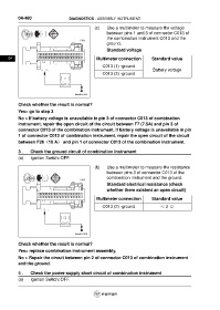
(c) Use a multimeter to measure the voltage
between pins 1 and 3 of connector C013 of
the combination instrument C013 and the
C013
ground.
Standard voltage
16 15 14 13 12 11 10 9 8 7 6 5 4 3 2 1
04 32 31 30 29 28 27 26 25 24 23 22 21 20 19 18 17 Multimeter connection Standard value
C013 (1) -ground
1 3 Battery voltage
C013 (3) -ground
ftwxd041039
Check whether the result is normal?
Yes> go to step 3
No > If battery voltage is unavailable in pin 3 of connector C013 of combination
instrument, repair the open circuit of the circuit between F7 (7.5A) and pin 3 of
connector C013 of the combination instrument. If battery voltage is unavailable in pin
1 of connector C013 of combination instrument, repair the open circuit of the circuit
between F26(10 A) and pin 1 of connector C013 of the combination instrument.
3 . Check the ground circuit of combination instrument
(a) Ignition Switch: OFF.
(b) Use a multimeter to measure the resistance
between pins 3 of connector C013 of the
combination instrument and the ground.
C013
Standard electrical resistance (check
whether there existent an open circuit)
16 15 14 13 12 11 10 9 8 7 6 5 4 3 2 1
32 31 30 29 28 27 26 25 24 23 22 21 20 19 18 17
Multimeter connection Standard value
C013 (2) -ground ≤ 2 Ω
2
ftwxd041419
Check whether the result is normal?
Yes> replace combination instrument assembly.
No > Repair the circuit between pin 2 of connector C013 of combination instrument
and the ground.
4 . Check the power-supply short circuit of combination instrument
(a) Ignition Switch: OFF.