
Page 771 - Workshop Manual - Tunland (2017)
P. 771
DIAGNOSTICS - ENGINE CONTROL SYSTEM 04-85
04
CAUTION
• To implement the following steps, ensure that ECM is grounded properly.
• Before conducting electric diagnosis, do refer to the reference circuit diagram
and the element information.
• Before conducting measurement, check the pins of connectors for rupture,
looseness and rust, and ensure that the pins are contacted properly.
• If the connection is good, check the sensor signal voltage when moving the
connector and harness. If a fault occurs, the voltage display on the diagnostic
instrument will change.
1 . DTC inspection
(a) Ignition switch: OFF.
(b) Connect the diagnostic apparatus.
(c) Use the diagnostic apparatus, read the fault code.
(d) Confirm whether there is fault code related to crankshaft position sensor?
Is the inspection result normal?
YES>To step 2.
NO>Intermittent trouble exists.
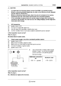
2 . Check power supply circuit for crankshaft position sensor
(a) Ignition switch: OFF.
(b) Disconnect the battery negative cable.
(c) Disconnect connector E02 of crankshaft position sensor.
(d) Connect the battery negative cable.
(e) Ignition switch: ON.
(f) Use a multimeter to measure the voltage
between the pin 1 of crankshaft position
sensor connector E02 and the ground.
Standard voltage
Multimeter connection
Standard value
pin
E02(1)- ground 4.75~5.25 V
Is the inspection result normal?
YES>To step 3.
No > Maintain or replace the harness.