
Page 775 - Workshop Manual - Tunland (2017)
P. 775
DIAGNOSTICS - ENGINE CONTROL SYSTEM 04-89
04
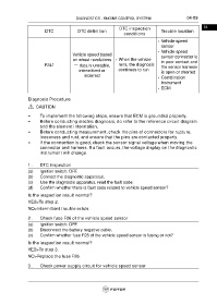
DTC inspection
DTC DTC definition Trouble location
conditions
• Vehicle speed
sensor
• Vehicle speed
Vehicle speed based sensor connector is
on wheel revolutions • When the vehicle in poor contact and
P241 — data is unstable, runs, the diagnosis the sensor harness
intermittent or continues to run
is open or shorted
incorrect
• Combination
instrument
• ECM
Diagnosis Procedure
CAUTION
• To implement the following steps, ensure that ECM is grounded properly.
• Before conducting electric diagnosis, do refer to the reference circuit diagram
and the element information.
• Before conducting measurement, check the pins of connectors for rupture,
looseness and rust, and ensure that the pins are contacted properly.
• If the connection is good, check the sensor signal voltage when moving the
connector and harness. If a fault occurs, the voltage display on the diagnostic
instrument will change.
1 . DTC inspection
(a) Ignition switch: OFF.
(b) Connect the diagnostic apparatus.
(c) Use the diagnostic apparatus, read the fault code.
(d) Confirm whether there is fault code related to vehicle speed sensor?
Is the inspection result normal?
YES>To step 2.
NO>Intermittent trouble exists.
2 . Check fuse F26 of the vehicle speed sensor
(a) Ignition switch: OFF.
(b) Disconnect the battery negative cable.
(c) Confirm whether fuse F26 of the vehicle speed sensor is fusing or not?
Is the inspection result normal?
YES>To step 3.
NO>Replace the fuse F26.
3 . Check power supply circuit for vehicle speed sensor