
Page 64 - Personal Study Notes (Engineering Metrology - 22342)
P. 64
Page 64 of 176
The “Go” gauge should always be so designed that it will cover as many dimensions as
possible in a single operation, whereas the “NOT-GO” gauge will cover only one
dimension.
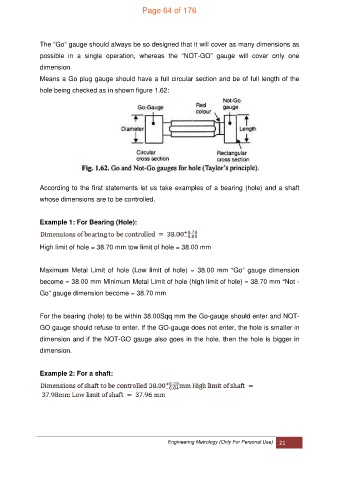
Means a Go plug gauge should have a full circular section and be of full length of the
hole being checked as in shown figure 1.62:
According to the first statements let us take examples of a bearing (hole) and a shaft
whose dimensions are to be controlled.
Example 1: For Bearing (Hole):
High limit of hole = 38.70 mm tow limit of hole = 38.00 mm
Maximum Metal Limit of hole (Low limit of hole) = 38.00 mm “Go” gauge dimension
become = 38.00 mm Minimum Metal Limit of hole (high limit of hole) = 38.70 mm “Not -
Go” gauge dimension become = 38.70 mm
For the bearing (hole) to be within 38.00Sqq mm the Go-gauge should enter and NOT-
GO gauge should refuse to enter. If the GO-gauge does not enter, the hole is smaller in
dimension and if the NOT-GO gauge also goes in the hole, then the hole is bigger in
dimension.
Example 2: For a shaft:
Engineering Metrology (Only For Personal Use) 21