
Page 26 - Zoo Animal Learning and Training
P. 26
Chapter 2: Orthopedic Implants in Neurosurgery 17
A Nonlocking screw
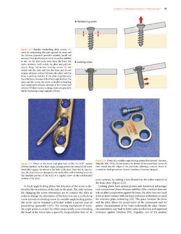
Figure 2.11 Regular nonlocking plate screws (A)
work by compressing the plate against the bone and
the friction generated provides stability (small red
arrows). Once the friction is lost or exceeded, stability
is lost. As the plate pulls away from the bone, the B Locking screw
screw reorients itself within the plate and pull‐out
occurs (large red arrow). Locking screws (B) are
locked into the plate and into the bone and do not
require intimate contact between the plate and the
bone to provide stability. If the plate is pulled away
from the bone, because of the fixed angle between the
plate and the screw, the screw is loaded in bending
and compressive stresses develop in the cortex (red
arrows). If failure occurs, locking constructs generally
fail by fracturing a large segment of bone.
Figure 2.13 Detail of a variable‐angle locking system (Pax System™; Securos,
Figure 2.12 Detail of the screw and plate hole of the LC‐DCP™ system Fiskdale, MA, USA). In this system, the thread of the screw head carves its
(DePuy Synthes). In this fixed‐angle locking system, the thread of the screw own thread into the ridges of the plate hole, allowing a narrow choice of
head fully engages the thread of the hole in the plate. Note that in this sys- orientation during insertion. Source: Courtesy of Securos Surgical.
tem, the plate holes are designed to be used either with a locking screw (in
the threaded portion of the hole) or a regular screw (in the nonthreaded
portion of the hole).
some systems, by cutting a new thread into the softer material of
the bone plate (Figure 2.13).
In fixed‐angle locking plates, the direction of the screw is dic- Locking plates have several proven and theoretical advantages
tated by the orientation of the hole in the plate. The only options over conventional plates. Because stability of the construct does not
for changing the screw orientation are to contour the plate in rely on plate compression against the bone, the plate does not need
order to change the orientation of the hole or to use a nonlocking to be in direct contact with the bone and there is therefore no need
screw instead of a locking screw. In variable‐angle locking plates, for extensive plate contouring [33]. The space between the bone
the screw can be oriented and locked within a narrow cone of and the plate allows for preservation of the periosteum and for
possibilities (generally ±10°). The locking mechanism of varia- greater vascularization of the bone underneath the plate. Greater
ble‐angle plates is created by either purposefully cross‐threading vascularization may lead to faster callus production and improved
the head of the screw into a specially designed plate hole or, in resistance against infection [35]. Arguably, one of the greatest