
Page 48 - Testing Electronic Components
P. 48
resistor while the other probe touching pin 3. Turn the knob clockwise
and anti-clockwise to see the changing of resistance.
The meter should show a smooth reading. If the reading is erratic, the
pointer will moved intermittently. You can service or replace the variable
resistor. Say if the variable resistor is 10kΩ the ohms, the value should
vary from 0Ω to 10kΩ or 10kΩ to 0Ω as you turn the knob clockwise and
anti-clockwise.
Now, using the probe that touches pin 3 short to pin 2 (Fig b) while the
other probe connects to pin 1, test for the result. The reading should be
the same except that the ohms range instead of starting at 0Ω should now
start at 10kΩ.
Here is some of the simple calculation to determine the meaning of the
code printed on the variable resistor:
12= 100 = 100 ohm
13=1000= 1000 ohm = 1 Kilo Ohm
54=50000=50000 ohm= 50 Kilo Ohm
102=10 00=1000 ohm= 1 Kilo Ohm
203=20 000=20000 ohm= 20 Kilo Ohm
523=52 000=52000 ohm= 52 Kilo Ohm
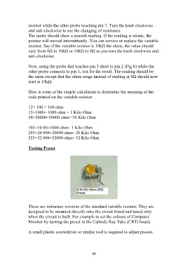
Testing Preset
These are miniature versions of the standard variable resistor. They are
designed to be mounted directly onto the circuit board and tuned only
when the circuit is built. For example to set the colours of Computer
Monitor by turning the preset in the Cathode Ray Tube (CRT) board.
A small plastic screwdriver or similar tool is required to adjust presets.
48