
Page 71 - Alliance US FULL
P. 71
SERVICE TIPS PAGE 1 OF 2
REPLACEMENT PROCEDURE FOR PISTON CUPS
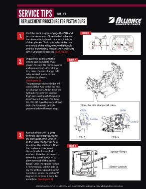
1. Start the truck engine, engage the PTO and FIGURE 1 Ball V/V FOR RAM CHANGE
turn the remote on. Close the ball valve on
the driver-side hydraulic ram near the front
of the cylinders. To do this: release the bolt
on the top of the valve, remove the handle
and the locking disc, reinstall the handle and
turn it 90 degrees (closed). (See figure 1)
2. Engage the pump with the FIGURE 2
remote and complete three
strokes (ensure the pump volume
and rpm are low). After doing
this, close the ram change ball
valve located in one of two
locations as shown.
(See figure 2)
The passenger-side cylinder will
come all the way to the top and
not change over. At this time the
hydraulic system will load up
(high pressure); push the pump
on/off switch to stop this. Turn
the PTO off. Turn the truck off and
drain the hydraulic tank air
pressure before the next step.
OPEN OPEN
CLOSED
CLOSED
3. Remove the four M16 bolts
from the spacer flange. Using
the provided 60mm wrench
on the spacer flange will help
to remove the hardware. Once FIGURE 3
the hardware is removed,
discard the bolts and lock Spacer flange
washers. Slide the piston cup
down the barrel about ½” to
allow removal of the spacer
flange. Once the spacer flange
is removed you will be able to 60mm wrench
pry the piston cup out into the
water box; rotate the piston 90
degrees to remove it from the
water box. (See figure 3)
Alliance Concrete Pumps Inc. will not be held liable for any loss, damage, or injury relating to these procedures.