
Page 1660 - Flipbook_SolidDesignSoutheast2020
P. 1660
DPSG 001
Flexible Containment appli C ation Guide Flexible Containment Solution S Guide
Disposable Process
Solutions Guide Containment
Systems
DoverPac SF (BioPharmaceutical) From Lab Scale Through Production Processes
Over view
The DoverPac SF for BioPharmaceutical applications consists of a series of standard and customized
®
applications based on the DoverPac SF (Split Flange) technology (FCSG 007). This expansion of single-use
®
manufacturing is designed to meet the needs of speed of implementation, ease of facility design, reduced
validation, cost savings over cleaning and cleaning verification, and reduced capital costs to the operation.
H O w DO e S i T w O rk?
The DoverPac SF can be attached to a variety of process vessels with by an integral sanitary
®
flange (either sealed or clamped to the liner) or via our patented multi o-ring technology.
Materials of Contact
The ArmorFlex Film is utilized to provide structural integrity, as well as meet the
®
rigorous demands for materials of contact. Using existing and specific reference,
monographs, key needs, such as no animal derived components, extractable/leachable
limits, and food contact compliance, to name a few, are addressed.
The Sanitary Flange Interface
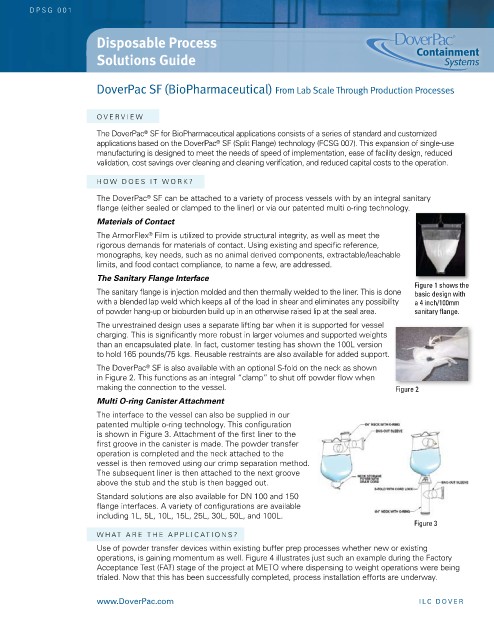
Figure 1 shows the
The sanitary flange is injection molded and then thermally welded to the liner. This is done basic design with
with a blended lap weld which keeps all of the load in shear and eliminates any possibility a 4 inch/100mm
of powder hang-up or bioburden build up in an otherwise raised lip at the seal area. sanitary flange.
The unrestrained design uses a separate lifting bar when it is supported for vessel
charging. This is significantly more robust in larger volumes and supported weights
than an encapsulated plate. in fact, customer testing has shown the 100L version
to hold 165 pounds/75 kgs. reusable restraints are also available for added support.
The DoverPac SF is also available with an optional S-fold on the neck as shown
®
in Figure 2. This functions as an integral “clamp” to shut off powder flow when
making the connection to the vessel. Figure 2
Multi O-ring Canister Attachment
The interface to the vessel can also be supplied in our
patented multiple o-ring technology. This configuration
is shown in Figure 3. Attachment of the first liner to the
first groove in the canister is made. The powder transfer
operation is completed and the neck attached to the
vessel is then removed using our crimp separation method.
The subsequent liner is then attached to the next groove
above the stub and the stub is then bagged out.
Standard solutions are also available for DN 100 and 150
flange interfaces. A variety of configurations are available
including 1L, 5L, 10L, 15L, 25L, 30L, 50L, and 100L.
Figure 3
wHAT A re TH e APPL i CAT i ONS ?
Use of powder transfer devices within existing buffer prep processes whether new or existing
operations, is gaining momentum as well. Figure 4 illustrates just such an example during the Factory
Acceptance Test (FAT) stage of the project at MeTO where dispensing to weight operations were being
trialed. Now that this has been successfully completed, process installation efforts are underway.
www.doverpac.com il C do V e R