Page 2104 - Flipbook_SolidDesignSoutheast2020
P. 2104

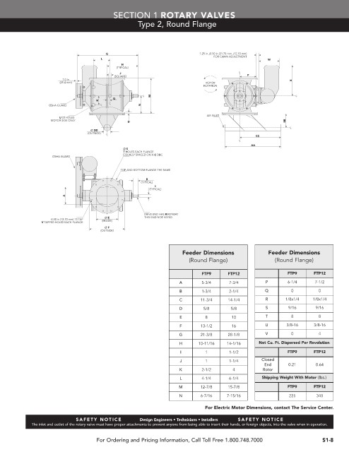
SECTION 1 ROTARY VALVES
                                                 Type 2, Round Flange


                                      G                                1.25 in ±0.50 in (31.75 mm ±12.70 mm)
                                                                            FOR CHAIN ADJUSTMENT
                                    L                                                          W
                                            H
                                          (TYPICAL)
                                           J
                                         (SQUARE)                                       P
                       1.0 in                                                                          X
                      (25.4 mm)                                          ROTOR
                                                                        ROTATION
                                                      M
                                         Q
                                   K
                  OSHA GUARD                      N
                                                                          AIR INLET
                      U (3) HOLES
                   MOTOR SIDE ONLY            D                                                      BB
                                 Ø DD
                                (OUTSIDE)
                                                                                           CC
                                                                                         AA
                                            Ø S
                                            T HOLES EACH FLANGE
                                            EQUALLY SPACED ON A C DBC
                   OSHA GUARD
                                           TOP AND BOTTOM FLANGE THE SAME
                                                    B
                                                  (TYPICAL)
                                                       I
                                                     (TYPICAL)
                        A


                                                    DRIVE END HAS R KEYWAY
                                      Ø E           THIS END NOT KEYED
                   0.50 in (12.70 mm) 13 TAP
                V TAPPED HOLES EACH FLANGE  (INSIDE)
                                      Ø F
                                    (OUTSIDE)

                                                                 Feeder Dimensions             Feeder Dimensions
                                                                   (Round Flange)                (Round Flange)


                                                                        FTP9     FTP12                FTP9     FTP12
                                                                A       5-3/4    7-3/4        P       6-1/4    7-1/2
                                                                B       1-3/4    2-1/4        Q        0         0
                                                                C      11-3/4    14-1/4       R      1/8x1/4   1/8x1/4
                                                                D       5/8       5/8         S       9/16      9/16
                                                                E        8        10          T        8         8
                                                                F      13-1/2     16          U       3/8-16   3/8-16
                                                                G      21-3/8    28-1/8       V        0         4
                                                                H      10-11/16  14-1/16    Net Cu. Ft. Dispersed Per Revolution
                                                                I        1       1-1/2                FTP9     FTP12
                                                                                             Closed
                                                                J        1       1-1/4
                                                                                              End     0.21      0.64
                                                                K       2-1/2      4         Rotor
                                                                L       4-1/4    6-1/4       Shipping Weight With Motor (lbs.)
                                                                M      12-7/8    15-7/8               FTP9     FTP12
                                                                N      6-7/16    7-15/16              225       340

                                                                         For Electric Motor Dimensions, contact The Service Center.

                            S A F E T Y   N O T I C E      Design Engineers • Technicians • Installers  S A F E T Y   N O T I C E
            The inlet and outlet of the rotary valve must have proper attachments to prevent anyone from being able to insert their hands, or foreign objects, into the valve when in operation.

                                   For Ordering and Pricing Information, Call Toll Free 1.800.748.7000            S1-8
   2099   2100   2101   2102   2103   2104   2105   2106   2107   2108   2109