
Page 80 - Nicolaes Witsen & Shipbuilding in the Dutch Golden Age
P. 80
Chapter Two
down to almost horizontal for c arriers. Together with the width of the bott om, setting the dea drise was another of the typical design moments in which the properties of the vessel were determined. The form of the bottom planking, the curvature toward the bow and the stern, had important consequences for sailing performance, but in an ordin ary contract this could not be specified and was left to the eye of the master. It is unique that these features for the pinas are given in Witsen’s book, which provides us with the ex- ceptional opportunity to study the shape of a seventeenth- century ship apart from distorted wrecks or contemporary models, which are unreliable in this respect.
In addition to the me asurements of the bottom, a s given in the pin as text, the re ader can find data impor- tant for the sh ape of the ship in section s 21 ( And make it quite even in heigh t, when it is shored ), 22 ( Then make the F rame, the F uttocks), 24 ( Then make the Master Ribband around, and make it level), 38 ( With the Top Timbers), and 39 (Make the Ribbands around, Shores and spalls). Together they supply the almost com- plete measurements of eight frames. The first frame is the main frame, located at one third of the total length from the front, with frame 2 at 12 feet forward and frame 3 an- other 11 feet 4 inches farther forward. Frame 4 is 12 feet 5 inches aft of the m ain frame, frame 5 another 11 feet 8 inches farther back, frame 6 at 11 feet 10 inches from frame 5, frame 7 at 18 feet 51⁄2 inches, and the last, frame 8, at 14 feet 61⁄2 inches from their respective preceding ones. Why the di stances between these fr ames were so irregular is not clear.
Witsen supplies us with four to seven different kinds of measurements for e ach frame at various measuring points on the hul l; with these dat a the fr ames can be re- constructed without difficulty (see t able 3 in the appen- dix and fig. 2.47). I used these me asurements in a set of drawings to check whether they are actually fair. In figure 2.48 the length is shortened by a factor of 500, while the height is reduced by 100. With the contracted hull shape, I could instantly verify whether the lines were f air. My first attempts to join the measurements as an acceptable drawing failed miserably, as there appeared to be no way of constructing a fair line between the given coordinates. Only when the sagging of the keel was incorporated in the calculations for the drawing (sagging plus or minus 15 cen- timeters in the middle) did the c oordinates allow for the lines to be connected in a flowing curve. This is additional proof that Witsen did not give just any measurements but derived them from a ship that was actually built.
It is interesting to notice at the same time that the Dutch shipbuilder did not use any circles in the c onstruction of the longitudinal shape but curves that were nong eomet-
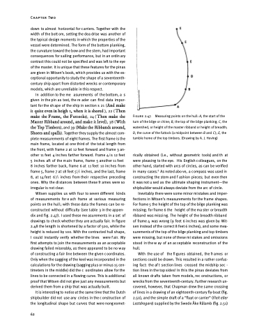
Figure 2.47.
turn of the bilge or chine; B, the top of the bilge planking; C, the watershed, or height of the master ribband or height of breadth; D, the curve of the futtock (a midpoint between B and C); E, the tumble home of the top timbers. (Drawing by A. J. Hoving)
rically obtained (i.e., without geometric tools) and th at were pleasing to the eye. His English c olleagues, on the other hand, started with arcs of circles, as can be verified in many cases.9 As noted abo ve, a c ompass was used in constructing the stem and f ashion pieces; but even then it was not u sed as the ultimate shaping instrument—the shipbuilder would always deviate from the arc of circle.
Inevitably there were some minor mistakes and imper- fections in Witsen’s measurements for the frame shapes. For frame 5 the height of the top of the bilge planking was missing; for frame 6 the height of the ma ster or breadth ribband was missi ng. The height of the breadth ribband of frame 4 was wrong ( 9 feet 6 inc hes was given by Wit- sen instead of the correct 8 feet 6 inches), and some mea- surements of the top of the bilge planking and top timbers were missing, but none of these mi stakes and omissions stood in the w ay of an ac ceptable reconstruction of the hull.
With the use of the fi gures obtained, the fr ames or sections could be drawn. This resulted in a rather confus- ing fact: the af t section lines crossed the midship sec - tion lines in the top sides! In this the pinas deviates from all known dr afts taken from models, rec onstructions, or wrecks from the seventeenth-century. Further research un- covered, however, that Chapman drew the same crossing of lines in a drawing of an eighteenth-century fly-boat (fig. 2.50), and the simple draft of a “fluyt or carrier” (Fleit eller Lastdragare) supplied by the Swede Åke Rålamb (fig. 2.51)
62
Measuring points on the hull: A, the start of the
