
Page 81 - Nicolaes Witsen & Shipbuilding in the Dutch Golden Age
P. 81
also shows the s ame phenomenon. We could speculate on the reason, but it is proba ble that this crossing was a result of the building method, in whic h, as we will see later, top timbers of an almost identical shape and curve were placed on the shel l made of the bottom and t urn of the bilge, which already rose forward and aft. The widest point of the fr ames would ri se accordingly forward and aft, which in the body plan causes the lines to cross.
With these data the shape of the hull can be projected, albeit this projection w ill still have the lines of the bot - tom, turn of the bilge, height of breadth, and the sheer rail plotted as if they were straight waterlines or bow-buttock lines, although they curve in both planes. From this draw- ing to a modern lines plan with straight sections in al l three planes is only a small step. The reader can compare the body plan to the lines plan (see drawing 1 in appen- dix) for the pinas.
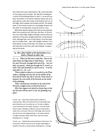
19. Also a floor timber at the main frame [hals] , with a Futtock on either side.
(151 I 22) When the Bottom is made fair , then at the main frame the bilge frame is made from a oor tim- ber and a Futtock, through each end of the oor two bolts are passed , which go through the F uttock, to hold it fast and immobile, as can be seen at b on the same plate [i.e., fig. 2.46].
Then a plank as shown at e is attached to the Floor timber, standing with one side on the middle of the keel and of which one side is vertical , from which to measure the even width of the futtocks on the inside of the planking.
Then a thin batten is attached to the ends of the Futtocks, straight across, as shown by letter f.
After that supports are placed as shown ing, so that the futtocks will not move w hen the planking is ap- plied.
Figure 2.48. (top) Frame shapes based on Witsen’s measurements. Above: All measurements of ship length have been divided by 500, the others by 100. The keel is slightly curved downward in the middle. Numbers 1–8 are the initial frame locations. Mistakes in Witsen’s text are marked with a small circle. A, the start of the turn of the bilge, seen from the side; B, the top of the bilge planking; C, the master ribband or height of breadth. Below: Same lines, seen from above. (Drawings by A. J. Hoving)
Figure 2.49. (bottom) Reconstructed frames of the pinas. The intersection of frame lines due to the steeply rising height of breadth in the stern is clearly visible. (Drawing by A. J. Hoving)
How Ships Are Built in Holland Today
63
