
Page 79 - Nicolaes Witsen & Shipbuilding in the Dutch Golden Age
P. 79
How Ships Are Built in Holland Today
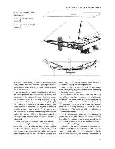
Figure 2.44. Outside plank.
Figure 2.45. (drawing R)
Figure 2.46. (drawing V)
(top) Plate XXVIII. (center) Plate L (bottom) Plate LII
with cleats. The cleats were placed approximately a meter apart, but they must have been set closer together in the bow and stern, where they had to check a lot more strain due to the curvature.
Anyone who tries to squeeze planks together with their thin sides against each other will notice that the material tries to escape the pressure sideways—the planks tip up. This was countered with the planking tongs (no. 9 in fi g. 1.20), which, much like large pincers, held the planks rigid and kept them from buckling at the edges. As a result, the planks, in section, lay in a straight line; this is confirmed by all the sections drawn by Witsen. Yet this feature can- not be ob served on any of the rem aining contemporary models. It is even more difficult to determine from wrecks, and on paintings and engr avings this part of the ship i s submerged.
Toward the bow the bottom pl anks were led to the stem in an increasingly wider curve and fitted in the stem rabbet; this is the case at least for the pinas and probably also for other rel atively sharp-cut vessels. For fluyts and other carriers it was unusual to have all the strak es run right through to the stem; the fi rst or second bilge strake
would then close off the bow b y going round the ends of the bottom planking and reaching the stem.
Toward the stern the bottom str akes followed the gar- board strake, filling the garboard stern rabbet and ending higher in the sternpost rabbet.
Planks that had to bend were he ated over fires: they were laid over a trestle, weighted down at the right places, and heated from below for lon g hours while keeping the upper side wet. The process demanded a lot of experience from the shipbuilder to giv e the pl anks their required bend without charring the in side too muc h. He h ad to mind the knots of the wood, too, whic h could influence the bend unexpectedly.
The ship’s bottom was supported from underneath by shores (little poles), whic h kept the sh ape from s agging. Meanwhile the symmetr y had to be ob served meticu- lously, since mistakes at this stage tended to multiply in the course of the building process.
The width of the bottom, measured at the main frame, was two thirds of the w idth of the ship —a little more for carriers, a little les s for yachts. The bottom c ould rise to- ward the sides (deadrise), from relatively a lot for fast ships
61
