
Page 128 - The ROV Manual - A User Guide for Remotely Operated Vehicles 2nd edition
P. 128
116 CHAPTER 5 Vehicle Design and Stability
With the appropriate buoyancy material chosen, the designer still needs to consider the final design and its effect on the stability of the vehicle. This is considered in the next section.
5.2 Buoyancy and stability
Designing an awesome looking vehicle with an integrated frame and buoyancy system is an excel- lent design goal. But if that vehicle turns turtle when deploying its payload, this is clearly not the desired path. Vehicle stability, as discussed below, is critical to the successful completion of any underwater task.
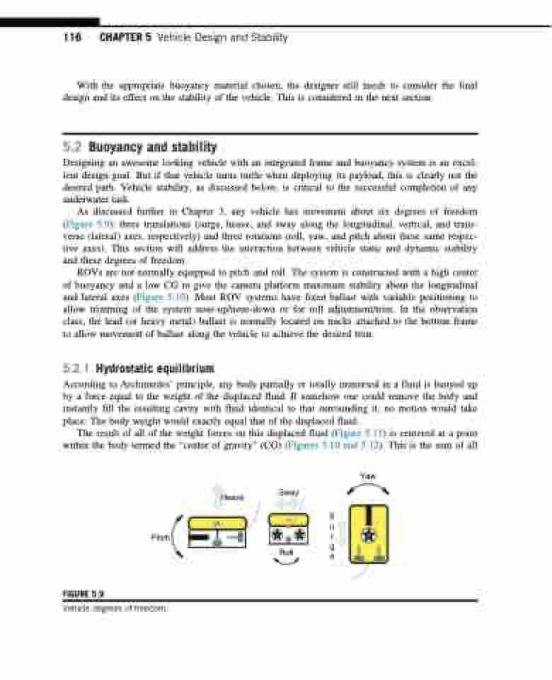
As discussed further in Chapter 3, any vehicle has movement about six degrees of freedom (Figure 5.9): three translations (surge, heave, and sway along the longitudinal, vertical, and trans- verse (lateral) axes, respectively) and three rotations (roll, yaw, and pitch about these same respec- tive axes). This section will address the interaction between vehicle static and dynamic stability and these degrees of freedom.
ROVs are not normally equipped to pitch and roll. The system is constructed with a high center of buoyancy and a low CG to give the camera platform maximum stability about the longitudinal and lateral axes (Figure 5.10). Most ROV systems have fixed ballast with variable positioning to allow trimming of the system nose-up/nose-down or for roll adjustment/trim. In the observation class, the lead (or heavy metal) ballast is normally located on tracks attached to the bottom frame to allow movement of ballast along the vehicle to achieve the desired trim.
5.2.1 Hydrostatic equilibrium
According to Archimedes’ principle, any body partially or totally immersed in a fluid is buoyed up by a force equal to the weight of the displaced fluid. If somehow one could remove the body and instantly fill the resulting cavity with fluid identical to that surrounding it, no motion would take place: The body weight would exactly equal that of the displaced fluid.
The result of all of the weight forces on this displaced fluid (Figure 5.11) is centered at a point within the body termed the “center of gravity” (CG) (Figures 5.10 and 5.12). This is the sum of all
Yaw
Pitch
Heave
CB
CG
Sway
CB
CG
Roll
S u r g e
FIGURE 5.9
Vehicle degrees of freedom.
