
Page 141 - The ROV Manual - A User Guide for Remotely Operated Vehicles 2nd edition
P. 141
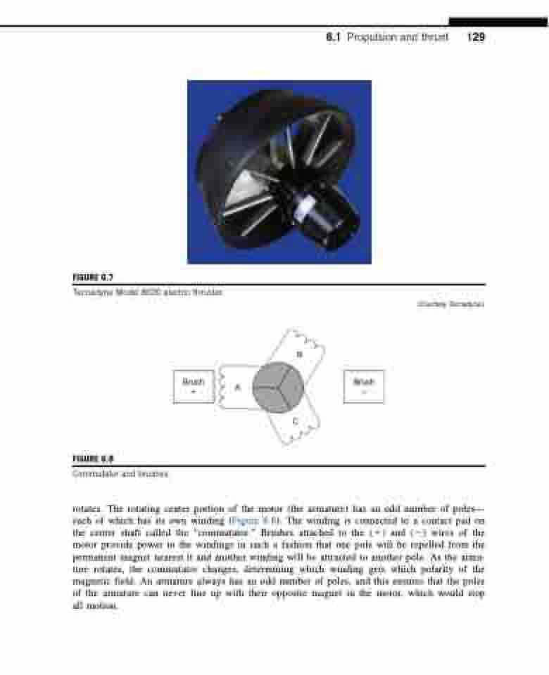
  FIGURE 6.7
Tecnadyne Model 8020 electric thruster.
6.1 Propulsion and thrust 129
  (Courtesy Tecnadyne.)
      Brush +
A
B
C
  FIGURE 6.8
Commutator and brushes.
 rotates. The rotating center portion of the motor (the armature) has an odd number of poles— each of which has its own winding (Figure 6.8). The winding is connected to a contact pad on the center shaft called the “commutator.” Brushes attached to the (1) and (2) wires of the motor provide power to the windings in such a fashion that one pole will be repelled from the permanent magnet nearest it and another winding will be attracted to another pole. As the arma- ture rotates, the commutator changes, determining which winding gets which polarity of the magnetic field. An armature always has an odd number of poles, and this ensures that the poles of the armature can never line up with their opposite magnet in the motor, which would stop all motion.
Brush –
