
Page 142 - The ROV Manual - A User Guide for Remotely Operated Vehicles 2nd edition
P. 142
130 CHAPTER 6 Thrusters
Near the center shaft of the armature are three plates attached to their respective windings (A, B, and C) around the poles. The brushes that feed power to the motor will be exactly opposite each other, which enables the magnetic fields in the armature to forever trail the static magnetic fields of the magnets. This causes the motor to turn. The more current that flows in the windings, the stronger the magnetic field in the armature, and the faster the motor turns.
Even as the current flowing in the windings creates an electromagnetic field that causes the motor to turn, the act of the windings moving through the static magnetic field of the motor causes a current in the windings. This current is opposite in polarity to the current the motor is drawing from the power source. The end result of this current, and the countercurrent (CEMF—counter electromotive force), is that as the motor turns faster it actually draws less current.
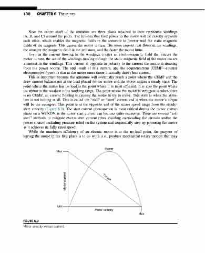
This is important because the armature will eventually reach a point where the CEMF and the draw current balance out at the load placed on the motor and the motor attains a steady state. The point where the motor has no load is the point where it is most efficient. It is also the point where the motor is the weakest in its working range. The point where the motor is strongest is when there is no CEMF; all current flowing is causing the motor to try to move. This state is when the arma- ture is not turning at all. This is called the “stall” or “start” current and is when the motor’s torque will be the strongest. This point is at the opposite end of the motor speed range from the steady- state velocity (Figure 6.9). The start current phenomenon is most critical during the motor startup phase on a WCROV as the motor start current can become quite excessive. There are several “soft start” methods to mitigate excess start current (thus avoiding overloading the circuits and/or the power source) including pressure relief on the system and sequentially step-up powering the motor as it achieves its fully rated speed.
While the maximum efficiency of an electric motor is at the no-load point, the purpose of having the motor in the first place is to do work (i.e., produce mechanical rotary motion that may
Max
Power
Min
FIGURE 6.9
Motor velocity
Max
Motor velocity versus current.
Motor current
Torque
