
Page 170 - The ROV Manual - A User Guide for Remotely Operated Vehicles 2nd edition
P. 170
158 CHAPTER 7 Power and Telemetry
I = 2A
V = 6V
R= ?
FIGURE 7.16
Sample electric circuit.
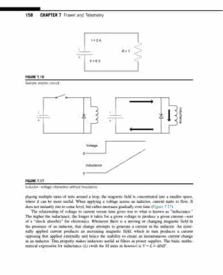
FIGURE 7.17
Voltage 0
Inductance 0
Inductorvoltage interaction without resistance.
placing multiple turns of wire around a loop, the magnetic field is concentrated into a smaller space, where it can be more useful. When applying a voltage across an inductor, current starts to flow. It does not instantly rise to some level, but rather increases gradually over time (Figure 7.17).
The relationship of voltage to current versus time gives rise to what is known as “inductance.” The higher the inductance, the longer it takes for a given voltage to produce a given current—sort of a “shock absorber” for electronics. Whenever there is a moving or changing magnetic field in the presence of an inductor, that change attempts to generate a current in the inductor. An exter- nally applied current produces an increasing magnetic field, which in turn produces a current opposing that applied externally and hence the inability to create an instantaneous current change in an inductor. This property makes inductors useful as filters in power supplies. The basic mathe- matical expression for inductance (L) (with the SI units in henries) is V 5 L 3 dI/dT.
Inductance
