
Page 172 - The ROV Manual - A User Guide for Remotely Operated Vehicles 2nd edition
P. 172
160 CHAPTER 7 Power and Telemetry
Voltage 00
Inductance 00
Voltage
Inductance
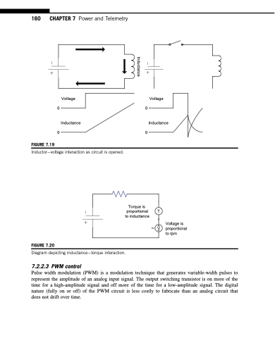
FIGURE 7.19
Inductorvoltage interaction as circuit is opened.
Torque is proportional to inductance
T
Voltage is DC V proportional
to rpm
FIGURE 7.20
Diagram depicting inductancetorque interaction.
7.2.2.3 PWM control
Pulse width modulation (PWM) is a modulation technique that generates variable-width pulses to represent the amplitude of an analog input signal. The output switching transistor is on more of the time for a high-amplitude signal and off more of the time for a low-amplitude signal. The digital nature (fully on or off) of the PWM circuit is less costly to fabricate than an analog circuit that does not drift over time.
Inductance
