
Page 173 - The ROV Manual - A User Guide for Remotely Operated Vehicles 2nd edition
P. 173
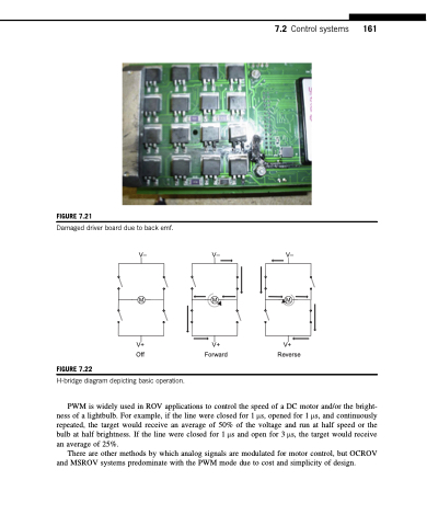
  FIGURE 7.21
Damaged driver board due to back emf.
V– V– V–
MMM
V+ V+ V+ Off Forward Reverse
7.2 Control systems 161
            FIGURE 7.22
 H-bridge diagram depicting basic operation.
PWM is widely used in ROV applications to control the speed of a DC motor and/or the bright- ness of a lightbulb. For example, if the line were closed for 1 μs, opened for 1 μs, and continuously repeated, the target would receive an average of 50% of the voltage and run at half speed or the bulb at half brightness. If the line were closed for 1 μs and open for 3 μs, the target would receive an average of 25%.
There are other methods by which analog signals are modulated for motor control, but OCROV and MSROV systems predominate with the PWM mode due to cost and simplicity of design.
