
Page 171 - The ROV Manual - A User Guide for Remotely Operated Vehicles 2nd edition
P. 171
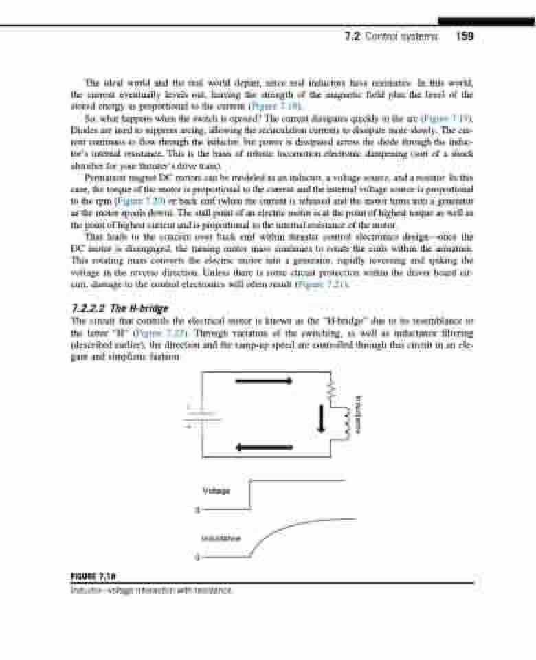
  The ideal world and the real world depart, since real inductors have resistance. In this world, the current eventually levels out, leaving the strength of the magnetic field plus the level of the stored energy as proportional to the current (Figure 7.18).
So, what happens when the switch is opened? The current dissipates quickly in the arc (Figure 7.19). Diodes are used to suppress arcing, allowing the recirculation currents to dissipate more slowly. The cur- rent continues to flow through the inductor, but power is dissipated across the diode through the induc- tor’s internal resistance. This is the basis of robotic locomotion electronic dampening (sort of a shock absorber for your thruster’s drive train).
Permanent magnet DC motors can be modeled as an inductor, a voltage source, and a resistor. In this case, the torque of the motor is proportional to the current and the internal voltage source is proportional to the rpm (Figure 7.20) or back emf (when the current is released and the motor turns into a generator as the motor spools down). The stall point of an electric motor is at the point of highest torque as well as the point of highest current and is proportional to the internal resistance of the motor.
That leads to the concern over back emf within thruster control electronics design—once the DC motor is disengaged, the turning motor mass continues to rotate the coils within the armature. This rotating mass converts the electric motor into a generator, rapidly reversing and spiking the voltage in the reverse direction. Unless there is some circuit protection within the driver board cir- cuit, damage to the control electronics will often result (Figure 7.21).
7.2.2.2 The H-bridge
The circuit that controls the electrical motor is known as the “H-bridge” due to its resemblance to the letter “H” (Figure 7.22). Through variation of the switching, as well as inductance filtering (described earlier), the direction and the ramp-up speed are controlled through this circuit in an ele- gant and simplistic fashion.
7.2 Control systems 159
      Voltage 0
Inductance 0
  FIGURE 7.18
 Inductorvoltage interaction with resistance.
Inductance
