
Page 247 - The ROV Manual - A User Guide for Remotely Operated Vehicles 2nd edition
P. 247
236
CHAPTER 9 LARS and TMS
(a) Reel (c) w/slip ring
(b)
Baling arm
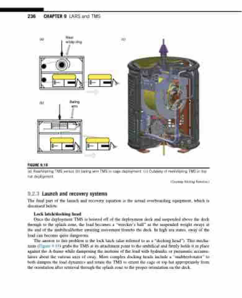
FIGURE 9.16
(a) Reel/slipring TMS versus (b) baling arm TMS in cage deployment. (c) Cutaway of reel/slipring TMS in top hat deployment.
(Courtesy Shilling Robotics.)
9.2.3 Launch and recovery systems
The final part of the launch and recovery equation is the actual overboarding equipment, which is
discussed below.
Lock latch/docking head
Once the deployment TMS is hoisted off of the deployment deck and suspended above the deck through to the splash zone, the load becomes a “wrecker’s ball” as the suspended weight sways at the end of the umbilical/tether awaiting movement from/to the deck. In high sea states, sway of the load can become quite dangerous.
The answer to this problem is the lock latch (also referred to as a “docking head”). This mecha- nism (Figure 9.19) grabs the TMS at its attachment point to the umbilical and firmly holds it in place against the A-frame while dampening the motions of the load with hydraulic or pneumatic accumu- lators about the various axes of sway. More complex docking heads include a “snubber/rotator” to both dampen the load dynamics and rotate the TMS to orient the cage or top hat appropriately from the orientation after retrieval through the splash zone to the proper orientation on the deck.
