
Page 249 - The ROV Manual - A User Guide for Remotely Operated Vehicles 2nd edition
P. 249
238 CHAPTER 9 LARS and TMS
FIGURE 9.19
Lock latch/docking head.
A-frame
TMS
Docking head with snubber
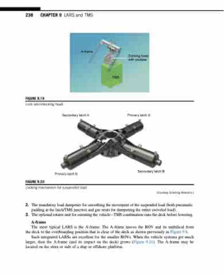
FIGURE 9.20
Secondary latch A
Primary latch A
Primary latch B
Secondary latch B
(Courtesy Schilling Robotics.)
Locking mechanism for suspended load.
2. Themandatoryloaddampenerforsmoothingthemovementofthesuspendedload(bothpneumatic padding at the latch/TMS junction and gas struts for dampening the entire swiveled load).
3. TheoptionalrotatorunitfororientingthevehicleTMScombinationontothedeckbeforelowering.
A-frame
The most typical LARS is the A-frame. The A-frame moves the ROV and its umbilical from the deck to the overboarding position that is clear of the deck as shown previously in Figure 9.6.
Such integrated LARSs are excellent for the smaller ROVs. When the vehicle systems get much larger, then the A-frame (and its impact on the deck) grows (Figure 9.21). The A-frame may be located on the stern or side of a ship or offshore platform.
