
Page 278 - The ROV Manual - A User Guide for Remotely Operated Vehicles 2nd edition
P. 278
10.2 How it works 267
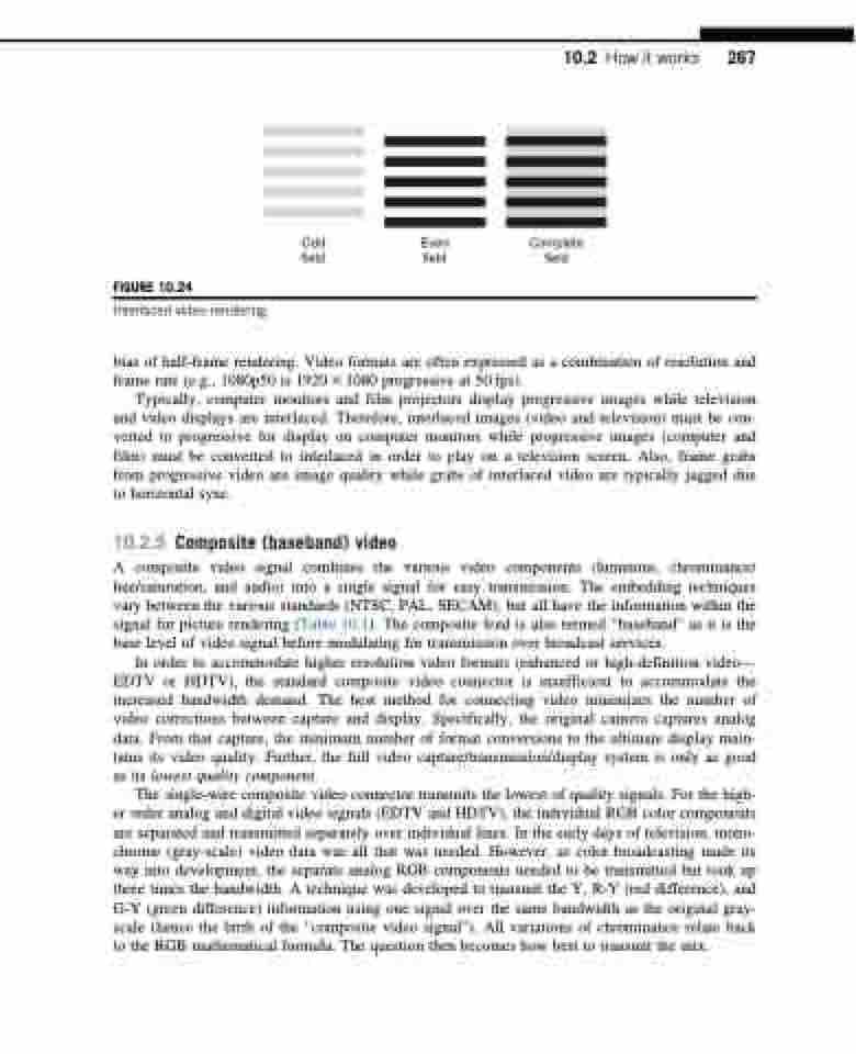
FIGURE 10.24
Interlaced video rendering.
Odd Even Complete field field field
bias of half-frame rendering. Video formats are often expressed as a combination of resolution and frame rate (e.g., 1080p50 is 1920 3 1080 progressive at 50 fps).
Typically, computer monitors and film projectors display progressive images while television and video displays are interlaced. Therefore, interlaced images (video and television) must be con- verted to progressive for display on computer monitors while progressive images (computer and film) must be converted to interlaced in order to play on a television screen. Also, frame grabs from progressive video are image quality while grabs of interlaced video are typically jagged due to horizontal sync.
10.2.5 Composite (baseband) video
A composite video signal combines the various video components (luminous, chrominance/ hue/saturation, and audio) into a single signal for easy transmission. The embedding techniques vary between the various standards (NTSC, PAL, SECAM), but all have the information within the signal for picture rendering (Table 10.1). The composite feed is also termed “baseband” as it is the base level of video signal before modulating for transmission over broadcast services.
In order to accommodate higher resolution video formats (enhanced or high-definition video— EDTV or HDTV), the standard composite video connector is insufficient to accommodate the increased bandwidth demand. The best method for connecting video minimizes the number of video corrections between capture and display. Specifically, the original camera captures analog data. From that capture, the minimum number of format conversions to the ultimate display main- tains its video quality. Further, the full video capture/transmission/display system is only as good as its lowest quality component.
The single-wire composite video connector transmits the lowest of quality signals. For the high- er order analog and digital video signals (EDTV and HDTV), the individual RGB color components are separated and transmitted separately over individual lines. In the early days of television, mono- chrome (gray-scale) video data was all that was needed. However, as color broadcasting made its way into development, the separate analog RGB components needed to be transmitted but took up three times the bandwidth. A technique was developed to transmit the Y, R-Y (red difference), and G-Y (green difference) information using one signal over the same bandwidth as the original gray- scale (hence the birth of the “composite video signal”). All variations of chrominance relate back to the RGB mathematical formula. The question then becomes how best to transmit the mix.
