
Page 315 - The ROV Manual - A User Guide for Remotely Operated Vehicles 2nd edition
P. 315
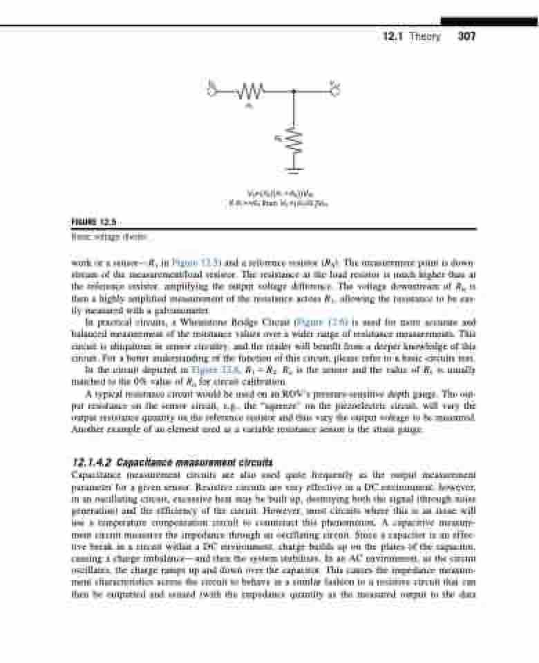
  FIGURE 12.5
Basic voltage divider.
Vin
Vout
RS
12.1 Theory 307
 R1
VS=(RS/(R1 + RS))VIN
if R1>>RS then VS=(RS/R1)VIN
 work or a sensor—R1 in Figure 12.5) and a reference resistor (RS). The measurement point is down- stream of the measurement/load resistor. The resistance at the load resistor is much higher than at the reference resistor, amplifying the output voltage difference. The voltage downstream of RS is then a highly amplified measurement of the resistance across R1, allowing the resistance to be eas- ily measured with a galvanometer.
In practical circuits, a Wheatstone Bridge Circuit (Figure 12.6) is used for more accurate and balanced measurement of the resistance values over a wider range of resistance measurements. This circuit is ubiquitous in sensor circuitry, and the reader will benefit from a deeper knowledge of this circuit. For a better understanding of the function of this circuit, please refer to a basic circuits text.
In the circuit depicted in Figure 12.6, R1 5 R2. Ru is the sensor and the value of Rv is usually matched to the 0% value of Ru for circuit calibration.
A typical resistance circuit would be used on an ROV’s pressure-sensitive depth gauge. The out- put resistance on the sensor circuit, e.g., the “squeeze” on the piezoelectric circuit, will vary the output resistance quantity on the reference resistor and thus vary the output voltage to be measured. Another example of an element used as a variable resistance sensor is the strain gauge.
12.1.4.2 Capacitance measurement circuits
Capacitance measurement circuits are also used quite frequently as the output measurement parameter for a given sensor. Resistive circuits are very effective in a DC environment; however, in an oscillating circuit, excessive heat may be built up, destroying both the signal (through noise generation) and the efficiency of the circuit. However, most circuits where this is an issue will use a temperature compensation circuit to counteract this phenomenon. A capacitive measure- ment circuit measures the impedance through an oscillating circuit. Since a capacitor is an effec- tive break in a circuit within a DC environment, charge builds up on the plates of the capacitor, causing a charge imbalance—and then the system stabilizes. In an AC environment, as the circuit oscillates, the charge ramps up and down over the capacitor. This causes the impedance measure- ment characteristics across the circuit to behave in a similar fashion to a resistive circuit that can then be outputted and sensed (with the impedance quantity as the measured output to the data
