
Page 317 - The ROV Manual - A User Guide for Remotely Operated Vehicles 2nd edition
P. 317
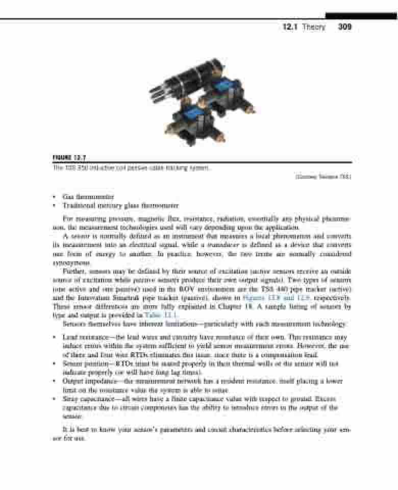
  FIGURE 12.7
The TSS 350 inductive coil passive cable tracking system.
• Gas thermometer
• Traditional mercury glass thermometer
(Courtesy Teledyne TSS.)
12.1 Theory 309
  For measuring pressure, magnetic flux, resistance, radiation, essentially any physical phenome- non, the measurement technologies used will vary depending upon the application.
A sensor is normally defined as an instrument that measures a local phenomenon and converts its measurement into an electrical signal, while a transducer is defined as a device that converts one form of energy to another. In practice, however, the two terms are normally considered synonymous.
Further, sensors may be defined by their source of excitation (active sensors receive an outside source of excitation while passive sensors produce their own output signals). Two types of sensors (one active and one passive) used in the ROV environment are the TSS 440 pipe tracker (active) and the Innovatum Smartrak pipe tracker (passive), shown in Figures 12.8 and 12.9, respectively. These sensor differences are more fully explained in Chapter 18. A sample listing of sensors by type and output is provided in Table 12.1.
Sensors themselves have inherent limitations—particularly with each measurement technology:
• Lead resistance—the lead wires and circuitry have resistance of their own. This resistance may induce errors within the system sufficient to yield sensor measurement errors. However, the use of three and four wire RTDs eliminates this issue, since there is a compensation lead.
• Sensor position—RTDs must be seated properly in their thermal wells or the sensor will not indicate properly (or will have long lag times).
• Output impedance—the measurement network has a resident resistance, itself placing a lower limit on the resistance value the system is able to sense.
• Stray capacitance—all wires have a finite capacitance value with respect to ground. Excess capacitance due to circuit components has the ability to introduce errors in the output of the sensor.
It is best to know your sensor’s parameters and circuit characteristics before selecting your sen- sor for use.
