
Page 319 - The ROV Manual - A User Guide for Remotely Operated Vehicles 2nd edition
P. 319
12.1 Theory 311
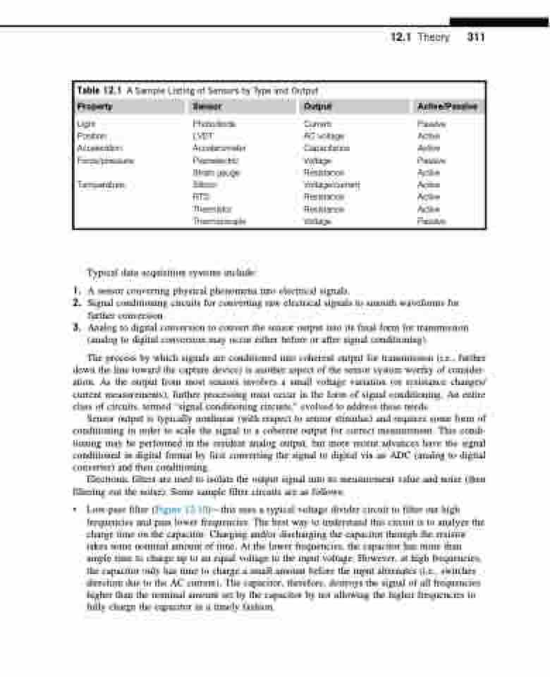
Table 12.1 A Sample Listing of Sensors by Type and Output
Property Sensor Output
Active/Passive
Light
Position Acceleration Force/pressure:
Temperature:
Photodiode LVDT Accelerometer Piezoelectric Strain gauge Silicon
RTD Thermistor Thermocouple
Current
AC voltage Capacitance Voltage Resistance Voltage/current Resistance Resistance Voltage
Passive Active Active Passive Active Active Active Active Passive
Typical data acquisition systems include:
1. A sensor converting physical phenomena into electrical signals.
2. Signal conditioning circuits for converting raw electrical signals to smooth waveforms for
further conversion.
3. Analog to digital conversion to convert the sensor output into its final form for transmission
(analog to digital conversion may occur either before or after signal conditioning).
The process by which signals are conditioned into coherent output for transmission (i.e., further
down the line toward the capture device) is another aspect of the sensor system worthy of consider- ation. As the output from most sensors involves a small voltage variation (or resistance changes/ current measurements), further processing must occur in the form of signal conditioning. An entire class of circuits, termed “signal conditioning circuits,” evolved to address these needs.
Sensor output is typically nonlinear (with respect to sensor stimulus) and requires some form of conditioning in order to scale the signal to a coherent output for correct measurement. This condi- tioning may be performed in the resident analog output, but more recent advances have the signal conditioned in digital format by first converting the signal to digital via an ADC (analog to digital converter) and then conditioning.
Electronic filters are used to isolate the output signal into its measurement value and noise (then filtering out the noise). Some sample filter circuits are as follows:
• Low-pass filter (Figure 12.10)—this uses a typical voltage divider circuit to filter out high frequencies and pass lower frequencies. The best way to understand this circuit is to analyze the charge time on the capacitor. Charging and/or discharging the capacitor through the resistor takes some nominal amount of time. At the lower frequencies, the capacitor has more than ample time to charge up to an equal voltage to the input voltage. However, at high frequencies, the capacitor only has time to charge a small amount before the input alternates (i.e., switches direction due to the AC current). The capacitor, therefore, destroys the signal of all frequencies higher than the nominal amount set by the capacitor by not allowing the higher frequencies to fully charge the capacitor in a timely fashion.
