
Page 321 - The ROV Manual - A User Guide for Remotely Operated Vehicles 2nd edition
P. 321
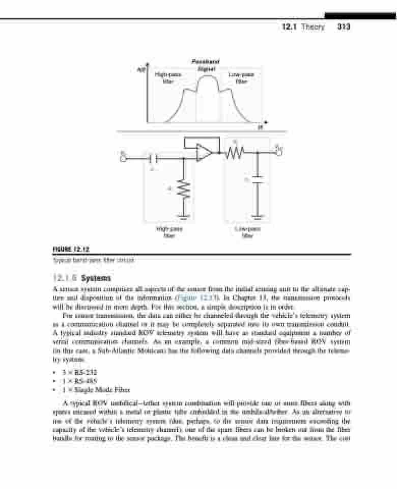
   A(f)
Passband Signal
  FIGURE 12.12
High-pass filter
(f)
12.1 Theory 313
   Vin
–
+
Vout
R2
C2
   C1
R1
High-pass filter
Low-pass filter
 Typical band-pass filter circuit.
12.1.6 Systems
A sensor system comprises all aspects of the sensor from the initial sensing unit to the ultimate cap- ture and disposition of the information (Figure 12.13). In Chapter 13, the transmission protocols will be discussed in more depth. For this section, a simple description is in order.
For sensor transmission, the data can either be channeled through the vehicle’s telemetry system as a communication channel or it may be completely separated into its own transmission conduit. A typical industry standard ROV telemetry system will have as standard equipment a number of serial communication channels. As an example, a common mid-sized fiber-based ROV system (in this case, a Sub-Atlantic Mohican) has the following data channels provided through the teleme- try system:
• 3 3 RS-232
• 1 3 RS-485
• 1 3 Single Mode Fiber
A typical ROV umbilicaltether system combination will provide one or more fibers along with spares encased within a metal or plastic tube embedded in the umbilical/tether. As an alternative to use of the vehicle’s telemetry system (due, perhaps, to the sensor data requirement exceeding the capacity of the vehicle’s telemetry channel), one of the spare fibers can be broken out from the fiber bundle for routing to the sensor package. The benefit is a clean and clear line for the sensor. The cost
Low-pass filter
