
Page 320 - The ROV Manual - A User Guide for Remotely Operated Vehicles 2nd edition
P. 320
312 CHAPTER 12 Sensor Theory
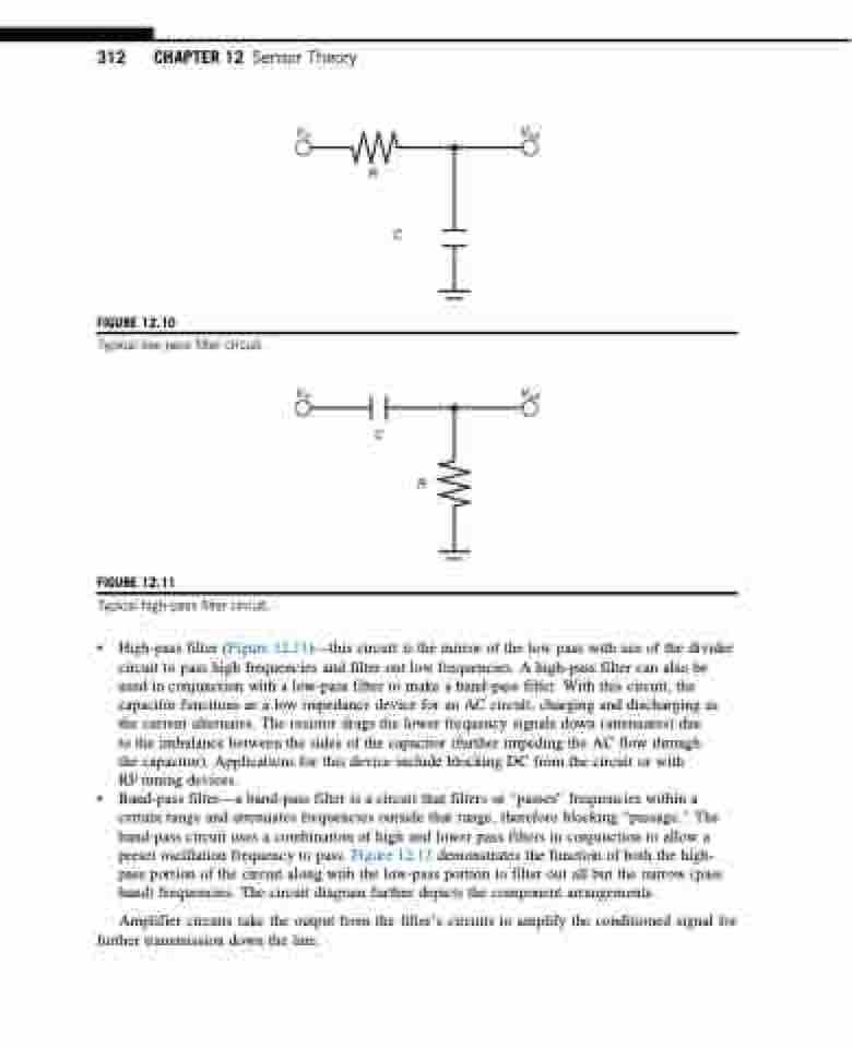
FIGURE 12.10
Typical low-pass filter circuit.
FIGURE 12.11
Typical high-pass filter circuit.
Vin
Vout
Vin
Vout
R
C
C
R
• High-pass filter (Figure 12.11)—this circuit is the mirror of the low pass with use of the divider circuit to pass high frequencies and filter out low frequencies. A high-pass filter can also be used in conjunction with a low-pass filter to make a band-pass filter. With this circuit, the capacitor functions as a low impedance device for an AC circuit, charging and discharging as the current alternates. The resistor drags the lower frequency signals down (attenuates) due
to the imbalance between the sides of the capacitor (further impeding the AC flow through the capacitor). Applications for this device include blocking DC from the circuit or with RF tuning devices.
• Band-pass filter—a band-pass filter is a circuit that filters or “passes” frequencies within a certain range and attenuates frequencies outside that range, therefore blocking “passage.” The band-pass circuit uses a combination of high and lower pass filters in conjunction to allow a preset oscillation frequency to pass. Figure 12.12 demonstrates the function of both the high- pass portion of the circuit along with the low-pass portion to filter out all but the narrow (pass band) frequencies. The circuit diagram further depicts the component arrangements.
Amplifier circuits take the output from the filter’s circuits to amplify the conditioned signal for further transmission down the line.
