
Page 398 - The ROV Manual - A User Guide for Remotely Operated Vehicles 2nd edition
P. 398
(a)
Echo strength
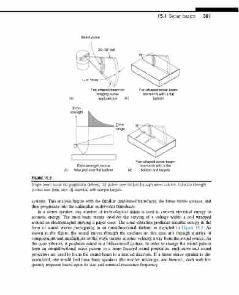
Beam pulse
20–30° tall
1–3° Wide
Fan-shaped beam for imaging sonar
applications (b)
Fan-shaped sonar beam intersects with a flat bottom
15.1 Sonar basics 391
Time range
FIGURE 15.2
(c)
Echo strength versus time plot over flat bottom
(d)
Fan-shaped sonar beam intersects with a flat bottom and targets
Single beam sonar (a) graphically defined, (b) pulsed over bottom through water column, (c) echo strength plotted over time, and (d) depicted with sample targets.
systems. This analysis begins with the familiar land-based transducer, the home stereo speaker, and then progresses into the unfamiliar underwater transducer.
In a stereo speaker, any number of technological twists is used to convert electrical energy to acoustic energy. The most basic means involves the varying of a voltage within a coil wrapped around an electromagnet moving a paper cone. The cone vibration produces acoustic energy in the form of sound waves propagating in an omnidirectional fashion as depicted in Figure 15.3. As shown in the figure, the sound moves through the medium (in this case air) through a series of compressions and rarefactions as the wave travels at sonic velocity away from the sound source. As the cone vibrates, it produces sound in a bidirectional pattern. In order to change the sound pattern from an omnidirectional wave pattern to a more focused sound projection, enclosures and sound projectors are used to focus the sound beam to a desired direction. If a home stereo speaker is dis- assembled, one would find three basic speakers (the woofer, midrange, and tweeter), each with fre- quency response based upon its size and nominal resonance frequency.
TARGET 1
TARGET 2
