
Page 399 - The ROV Manual - A User Guide for Remotely Operated Vehicles 2nd edition
P. 399
392 CHAPTER 15 Sonar
Expanding sound field
Pulsating sphere
Rarefactions
Compressions
Area of sound field
Pulse length
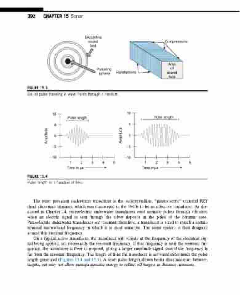
FIGURE 15.3
Sound pulse traveling in wave fronts through a medium.
10 5 00 55
10 5
Pulse length
10 10
12345 12345
Time in μs Time in μs
FIGURE 15.4
Pulse length as a function of time.
The most prevalent underwater transducer is the polycrystalline, “piezoelectric” material PZT (lead zirconium titanate), which was discovered in the 1940s to be an effective transducer. As dis- cussed in Chapter 14, piezoelectric underwater transducers emit acoustic pulses through vibration when an electric signal is sent through the silver deposits at the poles of the ceramic core. Piezoelectric underwater transducers are resonant; therefore, a transducer is sized to match a certain nominal narrowband frequency in which it is most sensitive. The sonar system is then designed around this nominal frequency.
On a typical active transducer, the transducer will vibrate at the frequency of the electrical sig- nal being applied, not necessarily the resonant frequency. If that frequency is near the resonant fre- quency, the transducer is freer to respond, giving a larger amplitude signal than if the frequency is far from the resonant frequency. The length of time the transducer is activated determines the pulse length generated (Figures 15.4 and 15.5). A short pulse length allows better discrimination between targets, but may not allow enough acoustic energy to reflect off targets as distance increases.
Amplitude
Amplitude
