
Page 455 - The ROV Manual - A User Guide for Remotely Operated Vehicles 2nd edition
P. 455
448 CHAPTER 16 Acoustic Positioning
Bow
S3
’
GPS
θ
Metacenter
S1
B/L #2
S2
Compute:
Orig. easting
- B/L #1 Length
- B/L #2 Length
- B/L #1 Orientation (Θ’)
- B/L #1 to #2 angle
- Metacenter easting and northing
- GPS offset (range/bearing θ) from metacenter
Stern
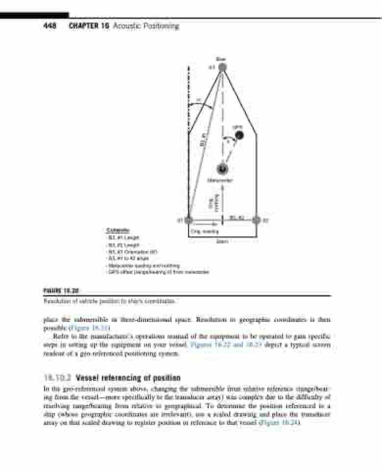
FIGURE 16.20
Resolution of vehicle position to ship’s coordinates.
place the submersible in three-dimensional space. Resolution to geographic coordinates is then possible (Figure 16.21).
Refer to the manufacturer’s operations manual of the equipment to be operated to gain specific steps in setting up the equipment on your vessel. Figures 16.22 and 16.23 depict a typical screen readout of a geo-referenced positioning system.
16.10.2 Vessel referencing of position
In the geo-referenced system above, changing the submersible from relative reference (range/bear- ing from the vessel—more specifically to the transducer array) was complex due to the difficulty of resolving range/bearing from relative to geographical. To determine the position referenced to a ship (whose geographic coordinates are irrelevant), use a scaled drawing and place the transducer array on that scaled drawing to register position in reference to that vessel (Figure 16.24).
B/L #1
Orig. northing
