
Page 502 - The ROV Manual - A User Guide for Remotely Operated Vehicles 2nd edition
P. 502
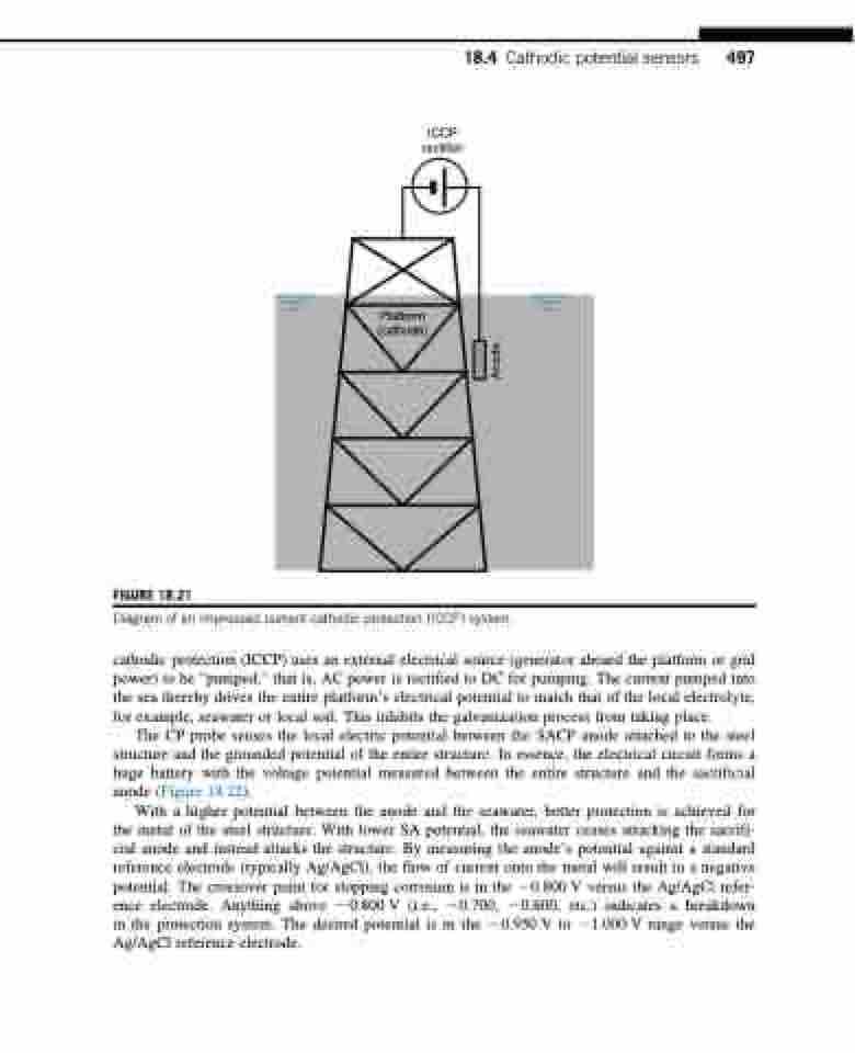
  ICCP rectifier
18.4 Cathodic potential sensors 497
        FIGURE 18.21
Platform (cathode)
      Diagram of an impressed current cathodic protection (ICCP) system.
cathodic protection (ICCP) uses an external electrical source (generator aboard the platform or grid power) to be “pumped,” that is, AC power is rectified to DC for pumping. The current pumped into the sea thereby drives the entire platform’s electrical potential to match that of the local electrolyte, for example, seawater or local soil. This inhibits the galvanization process from taking place.
The CP probe senses the local electric potential between the SACP anode attached to the steel structure and the grounded potential of the entire structure. In essence, the electrical circuit forms a huge battery with the voltage potential measured between the entire structure and the sacrificial anode (Figure 18.22).
With a higher potential between the anode and the seawater, better protection is achieved for the metal of the steel structure. With lower SA potential, the seawater ceases attacking the sacrifi- cial anode and instead attacks the structure. By measuring the anode’s potential against a standard reference electrode (typically Ag/AgCl), the flow of current onto the metal will result in a negative potential. The crossover point for stopping corrosion is in the 20.800 V versus the Ag/AgCl refer- ence electrode. Anything above 20.800 V (i.e., 20.700, 20.600, etc.) indicates a breakdown in the protection system. The desired potential is in the 20.950 V to 21.000 V range versus the Ag/AgCl reference electrode.
Anode
