
Page 511 - The ROV Manual - A User Guide for Remotely Operated Vehicles 2nd edition
P. 511
508 CHAPTER 19 Manipulators
Most full-function manipulators used with ROVs are 7-function manipulator systems. The seven functions break down into six DoF (six links and six joints, arranged sequentially, with the last two links having zero length) functions (three for orientation and three for positioning) and one end effector function. A manipulator with more than six DoF is certainly possible, but it is considered kinematically redundant as the additional joints do not gain more access to the workspace (defined below).
OCROVs typically have one single- or multifunction manipulator system. Unless the vehicle is fixed to a stationary object while performing work (e.g., atop a fixed structure while thrusting down to hold the vehicle in place), coordinating the arm while the vehicle free-flies is considered difficult (if not impossible) as the vehicle frame of reference (FoR) is floating with regard to the object’s FoR.
Just as a carpenter uses one hand to steady the board while the other performs the sawing/screw- ing/nailing function, practically all WCROVs are equipped with a dual manipulator system having one “rate” arm (for grabbing and holding onto the object, thus locking the vehicle’s FoR to the object’s FoR) and one dexterous “position/proportion” arm for performing the complex work task.
A base that links directly to an end effector is typically termed simply a “tool” (e.g., a brush, drill, torque tool, or other mechanical device) or a “grabber” (for end effectors that just attach to some structure). This section will consider the manipulator system, while in Chapter 20, tooling will be further examined.
19.1.2.1 The base
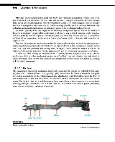
The manipulator base is the mechanical hard point connecting the vehicle (or pedestal) to the series of joints, links, and end effector. It is typically rigidly mounted as the forces of the entire manipula- tor system concentrate on the vehicle/manipulator attachment point. Depending upon the DoF of the manipulator system, the base should be braced in several orientations to account for torsion stress. The typical base for a multifunction subsea manipulator system connects to a rotary joint, allowing left/right movement, and is either fixed in the horizontal or vertical plane (depending upon desired orientation and range of motion).
FIGURE 19.5
Wrist Yaw Pitch
Elbow
Upper arm
Shoulder
Azimuth
(Courtesy Schilling Robotics.)
Jaw
Forearm
Basic manipulator system.
