Page 512 - The ROV Manual - A User Guide for Remotely Operated Vehicles 2nd edition
P. 512
  19.1.2.2 Links
Links join to either the base, joints or end effector and form the load-bearing portions of the chain.
19.1.2.3 Joints
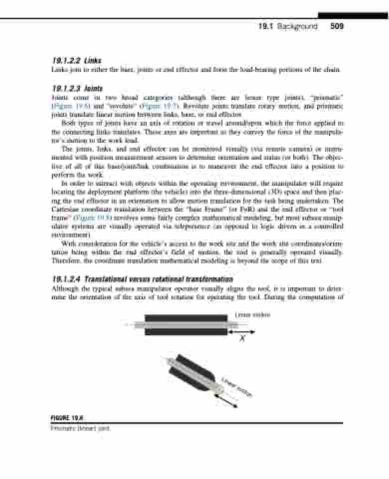
Joints come in two broad categories (although there are lesser type joints), “prismatic” (Figure 19.6) and “revolute” (Figure 19.7). Revolute joints translate rotary motion, and prismatic joints translate linear motion between links, base, or end effector.
Both types of joints have an axis of rotation or travel around/upon which the force applied to the connecting links translates. These axes are important as they convey the force of the manipula- tor’s motion to the work load.
The joints, links, and end effector can be monitored visually (via remote camera) or instru- mented with position measurement sensors to determine orientation and status (or both). The objec- tive of all of this base/joint/link combination is to maneuver the end effector into a position to perform the work.
In order to interact with objects within the operating environment, the manipulator will require locating the deployment platform (the vehicle) into the three-dimensional (3D) space and then plac- ing the end effector in an orientation to allow motion translation for the task being undertaken. The Cartesian coordinate translation between the “base Frame” (or FoR) and the end effector or “tool frame” (Figure 19.8) involves some fairly complex mathematical modeling, but most subsea manip- ulator systems are visually operated via telepresence (as opposed to logic driven in a controlled environment).
With consideration for the vehicle’s access to the work site and the work site coordinates/orien- tation being within the end effector’s field of motion, the tool is generally operated visually. Therefore, the coordinate translation mathematical modeling is beyond the scope of this text.
19.1.2.4 Translational versus rotational transformation
Although the typical subsea manipulator operator visually aligns the tool, it is important to deter- mine the orientation of the axis of tool rotation for operating the tool. During the computation of
Linear motion
19.1 Background 509
    FIGURE 19.6
Prismatic (linear) joint.
 Linear motion


