
Page 594 - The ROV Manual - A User Guide for Remotely Operated Vehicles 2nd edition
P. 594
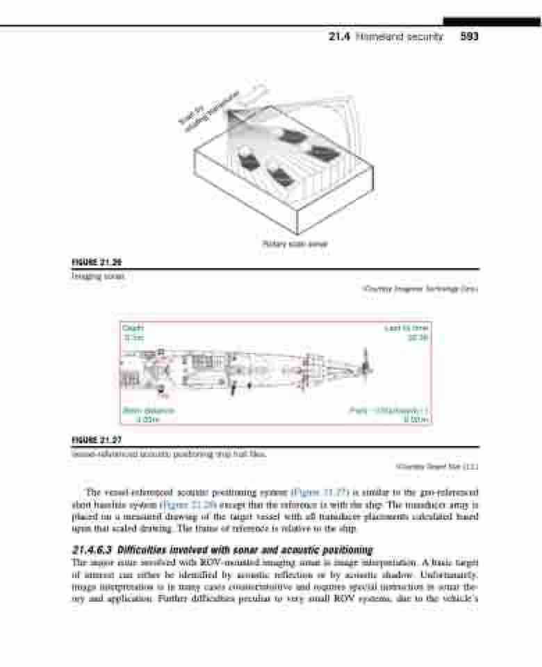
FIGURE 21.26
Imaging sonar.
Rotary scan sonar
21.4 Homeland security 593
FIGURE 21.27
Depth 0.3 m
Last fix time 02:38
(Courtesy Imagenex Technology Corp.)
AP
AS
FP PS
Stern distance
0.00m 0.00m
Vessel-referenced acoustic positioning ship hull files.
The vessel-referenced acoustic positioning system (Figure 21.27) is similar to the geo-referenced short baseline system (Figure 21.28) except that the reference is with the ship. The transducer array is placed on a measured drawing of the target vessel with all transducer placements calculated based upon that scaled drawing. The frame of reference is relative to the ship.
21.4.6.3 Difficulties involved with sonar and acoustic positioning
The major issue involved with ROV-mounted imaging sonar is image interpretation. A basic target of interest can either be identified by acoustic reflection or by acoustic shadow. Unfortunately, image interpretation is in many cases counterintuitive and requires special instruction in sonar the- ory and application. Further difficulties peculiar to very small ROV systems, due to the vehicle’s
Port()/Starboard()
(Courtesy Desert Star LLC.)
Scan by
rotating transducer
