
Page 90 - The ROV Manual - A User Guide for Remotely Operated Vehicles 2nd edition
P. 90
78 CHAPTER 3 Design Theory and Standards
FIGURE 3.15
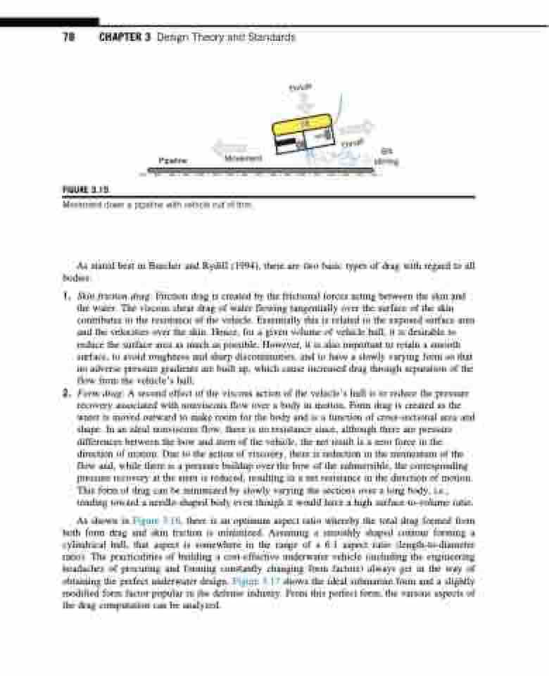
Silt Pipeline Movement stirring
Movement down a pipeline with vehicle out of trim.
As stated best in Burcher and Rydill (1994), there are two basic types of drag with regard to all bodies:
1. Skin friction drag: Friction drag is created by the frictional forces acting between the skin and the water. The viscous shear drag of water flowing tangentially over the surface of the skin contributes to the resistance of the vehicle. Essentially this is related to the exposed surface area and the velocities over the skin. Hence, for a given volume of vehicle hull, it is desirable to reduce the surface area as much as possible. However, it is also important to retain a smooth surface, to avoid roughness and sharp discontinuities, and to have a slowly varying form so that no adverse pressure gradients are built up, which cause increased drag through separation of the flow from the vehicle’s hull.
2. Form drag: A second effect of the viscous action of the vehicle’s hull is to reduce the pressure recovery associated with nonviscous flow over a body in motion. Form drag is created as the water is moved outward to make room for the body and is a function of cross-sectional area and shape. In an ideal nonviscous flow, there is no resistance since, although there are pressure differences between the bow and stern of the vehicle, the net result is a zero force in the direction of motion. Due to the action of viscosity, there is reduction in the momentum of the flow and, while there is a pressure buildup over the bow of the submersible, the corresponding pressure recovery at the stern is reduced, resulting in a net resistance in the direction of motion. This form of drag can be minimized by slowly varying the sections over a long body, i.e., tending toward a needle-shaped body even though it would have a high surface-to-volume ratio.
As shown in Figure 3.16, there is an optimum aspect ratio whereby the total drag formed from both form drag and skin friction is minimized. Assuming a smoothly shaped contour forming a cylindrical hull, that aspect is somewhere in the range of a 6:1 aspect ratio (length-to-diameter ratio). The practicalities of building a cost-effective underwater vehicle (including the engineering headaches of procuring and forming constantly changing form factors) always get in the way of obtaining the perfect underwater design. Figure 3.17 shows the ideal submarine form and a slightly modified form factor popular in the defense industry. From this perfect form, the various aspects of the drag computation can be analyzed.
Thrust
CG
CB
Thrust
