
Page 99 - The ROV Manual - A User Guide for Remotely Operated Vehicles 2nd edition
P. 99
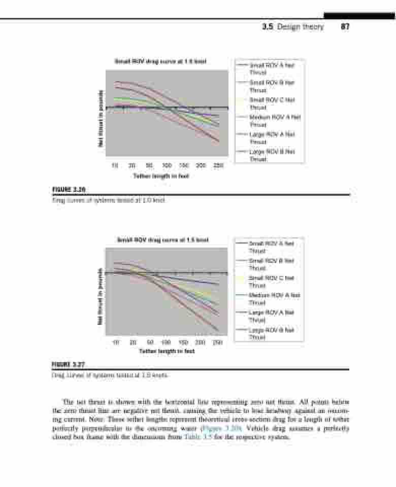
  Small ROV drag curve at 1.0 knot
3.5 Design theory 87
   FIGURE 3.26
10 20 50 100 150 200 250
Tether length in feet
 Drag curves of systems tested at 1.0 knot.
Small ROV drag curve at 1.5 knot
  FIGURE 3.27
10 20 50 100 150 200 250
Tether length in feet
Small ROV A Net Thrust
Small ROV B Net Thrust
Small ROV C Net Thrust
Medium ROV A Net Thrust
Large ROV A Net Thrust
Large ROV B Net Thrust
   Drag curves of systems tested at 1.5 knots.
The net thrust is shown with the horizontal line representing zero net thrust. All points below the zero thrust line are negative net thrust, causing the vehicle to lose headway against an oncom- ing current. Note: These tether lengths represent theoretical cross-section drag for a length of tether perfectly perpendicular to the oncoming water (Figure 3.20). Vehicle drag assumes a perfectly closed box frame with the dimensions from Table 3.5 for the respective system.
Small ROV A Net Thrust
Small ROV B Net Thrust
Small ROV C Net Thrust
Medium ROV A Net Thrust
Large ROV A Net Thrust
Large ROV B Net Thrust
Net thrust in pounds Net thrust in pounds
