
Page 17 - 233423 - Exhaust Fans_Neat
P. 17
WIRING HARNESS - DISCONNECT DEVICE
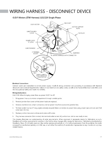
O.D.P. Motors (ITW Harness) 115/220 Single Phase
FAN SHAFT
O.D.P. MOTOR
MOTOR SUPPORT
PLATE
JUNCTION BOX
COVER TOP PLATE
POWER LEADS
8” LONG
JUNCTION BOX
CONDUIT
4 TERMINAL GUIDE
SOCKET BEARINGS
WIRING HARNESS WITH CONNECTOR
JUNCTION
BOX
COVER
4 TERMINAL
SOCKET
JUNCTION
BOX
WIRING HARNESS
WITH CONNECTOR
(FROM MOTOR)
Electrical Connections
Connect motor per nameplate to correct power supply. Install all wiring, protection and grounding in accordance with National
Electrical Code and local requirements. Follow all local electrical and safety codes, as well as the National Electrical Code (NEC) and
the Occupational Safety and Health Act (OSHA).
Wiring Instructions
CAUTION: When bringing power lines up, power MUST be off.
1. Bring power lines up to motor compartment through conduit guide.
2. Remove junction box cover so that power leads are exposed.
3. Remove one knock-out, attach connector, and run power lines from source into junction box.
4. Terminal socket has two 8” long pigtails already stripped. Make connection to power lines using proper size wire nuts and fold
wires back into box.
5. Replace junction box cover and secure in place with screw.
6. Plug harness connector (from motor) into terminal socket at end of junction box. Unit is now ready to test.
This drawing illustrates our understanding of order requirements. When approved, it represents details for fabrication; as such,
PennBarry will not be responsible for revisions in the field or other changes after release for fabrication. Published and protected by
PennBarry, Plano, TX. All rights reserved. May not be reproduced partially or in full without permission from the publisher. No rights
conveyed to manufacture partially or in full, use, or sell either the method of construction represented or any invention in any way
related thereto.
www.PennBarry.com 17