
Page 57 - 233423 - Exhaust Fans_Neat
P. 57
Normally, power is brought up from within the building through conduit lines and located at the terminal box. Before wiring is
attempted, always lock out primary and secondary power source. Utilizing the pre-punched hole found at the terminal box on the
fan housing, insert a 3/8” electrical connector. All wiring furnished should be in strict accordance with the National Electrical Code
and local, state and federal standards. Complete the installation by cutting a 9 1/2” by 12 1/2” ceiling opening for the Z3, Z5 and Z6;
11 7/8” by 13 3/4” for the Z8 and Z81; 14 1/2” by 18” for the Z10; and 14 1/2” by 23 3/4” for Z101, Z102, Z12 and Z121 ceiling fan.
Installation of ceiling fans in suspended ceiling systems require a minimum 10 gauge solid wire for hanging or suspending the ceiling
fan. Four wires per unit should be connected to the pre-punched holes of the adjustable mounting flanges (after the flanges have
been mounted to the fan housing as outlined above). Note: For the Z12 and Z121, 1/4” threaded rods or perforated steel strips should
be used per fan as illustrated in Figure 4.
If installation is to be made with ceiling in place, access must be from above. The following procedure should be used for installing
the Zephyr Ceiling Fans. Assemble the adjustable flanges to the fan housing as illustrated in Figures 2 or 2A. Position adjustable
flanges so the unit is flush with top side of ceiling surface. Tighten the adjustable flanges and secure them with the appropriate
hardware (wood screws or sheet metal screws, depending on framing construction). Use the housing as a template, punch or drill a
small hole through the ceiling at each corner of the housing and cut an opening in the ceiling, using these holes as a guide. Install
the duct and electrical service in accordance with the instructions listed in the previous section.
In installations where the ceiling is already installed and there is no access from above, the following procedure should be followed.
Before cutting ceiling opening, determine the exact location of framing or support members. Cut hole in ceiling using care not to
exceed the dimensions of the ceiling grille. Note: The ceiling hole should be cut so that one edge of the hole is in line with the inside
face of the joist. The hole must be large enough to permit passage of the fan housing into the ceiling space. Care should be taken
not to exceed the ceiling grill dimensions when cutting.
Remove the blower assembly from the housing. For single blower units, remove two #10 sheet metal screws near the blower, slide
power pack to the left to release it from the housing. (For double blower units, remove one 1/4” bolt).
Electrical service should now be brought up to the fan location. This should be done in accordance with the instructions listed in the
previous section.
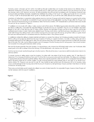
To secure housing in ceiling space, raise the housing into place with one edge of the housing against joist “A” (see Figure 3).
Determine if it is necessary to build out from joist “B” so that the housing can be secured from both sides. If building out is necessary,
an appropriate piece(s) of wood should be utilized. These wood spacers should be nailed to joist “B” to increase the thickness of the
joist at the point where the fan will be installed. The fan housing should fit snugly between joist “A” and joist “B” (or the built-out-
section of joist “B”). If spacers are required for joist “B”, they should be sized according to the dimension of the fan housing. Using
care to avoid damage to the housing, secure the housing to the joists by nailing through the pre-punched holes found at the top
and bottom of housing sides.
These pre-punched holes would normally be utilized as a point of attachment for the adjustable flanges; however, these flanges will
not be necessary with this type of installation.
Figure 3
Figure 5a
Figure 5b
Figure 4
4 www.PennBarry.com