
Page 58 - 233423 - Exhaust Fans_Neat
P. 58
Before the nails are driven snug, care should be taken to ensure that the housing is 1/4” above the ceiling level. Nails should
now be secured. Care should be taken to ensure that the nail head is large enough to prevent slipping through the pre-punched
holes. A washer can be used to increase the bearing surface. Re-attach blower assembly to housing. Lock out primary and secondary
power source and secure electrical lines to the terminal box. This should be done in accordance with the procedure outlined
For all of the installation situations described above, the egg crate ceiling grill should be installed as a final step. This is done by first
assembling the two torsion springs to the grill. Use the torsion springs and grill buttons from the hardware kit provided. Insert the
grille buttons into the ceiling grill as shown in Figure 5a through the slot in the grill buttons. The grill is now ready for assembly to
the housing. Lift the grill into position below the housing. Insert the two torsion springs into the keyhole slots located in the center
of the housing as shown in Figure 5B. Push the grill towards the housing
Electrical Connections
Before attempting any repair or installation work, be certain that all power to the motor and electrical
accessories are turned off and locked in off position.
CAUTION
1. Connect Motor per nameplate to correct power supply.
2. Install all wiring, protection and grounding in accordance with national electrical code and local requirements.
3. Follow all local electrical and safety codes, as well as the National Electrical Code (NEC) and the Occupational Safety and Health
Act (OSHA).
4. In order to prevent motor failure when speed controller is used, unit must be started on high speed before turning to low
speed.
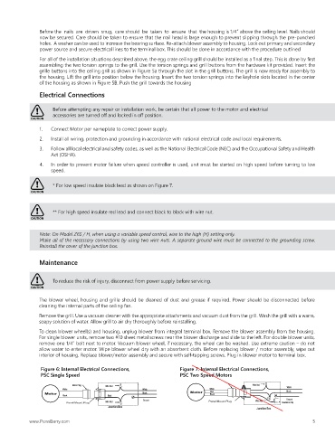
* For low speed insulate black lead as shown on Figure 7.
CAUTION
** For high speed insulate red lead and connect black to black with wire nut.
CAUTION
Note: On Model Z6S / H, when using a variable speed control, wire to the high (H) setting only.
Make all of the necessary connections by using two wire nuts. A separate ground wire must be connected to the grounding screw.
Reinstall the cover of the junction box.
Maintenance
To reduce the risk of injury, disconnect from power supply before servicing.
CAUTION
The blower wheel, housing and grille should be cleaned of dust and grease if required. Power should be disconnected before
cleaning the internal parts of the ceiling fan.
Remove the grill. Use a vacuum cleaner with the appropriate attachments and vacuum dust from the grill. Wash the grill with a warm,
soapy solution of water. Allow grill to air dry thoroughly before reinstalling.
To clean blower wheel(s) and housing, unplug blower from integral terminal box. Remove the blower assembly from the housing.
For single blower units, remove two #10 sheet metal screws near the blower discharge and slide to the left. For double blower units,
remove one 1/4” bolt next to motor. Vacuum blower wheel, if necessary, the wheel can be washed. Use extreme caution – do not
allow water to enter motor. Wipe blower wheel dry with an absorbent cloth. Before replacing blower / motor assembly, wipe out
interior of housing. Replace blower/motor assembly and secure with self-tapping screws. Plug in blower motor to terminal box.
Figure 6: Internal Electrical Connections, Figure 7: Internal Electrical Connections,
PSC Single Speed PSC Two Speed Motors
Motor Plug Wire Nut Wire Nut
White
White White White Black
Black Red
Black
Black
Ground Wire Nut Ground
Wire Nut Insulation Clip
Junction Box
Junction Box
www.PennBarry.com 5