
Page 135 - Divyank Tyagi
P. 135
|
ModeliNG siTe coNTexT 101
1. Start a new project using either the Default.rte or MetricDefault.rte template file,
and activate the Site plan view in the Project Browser. If you’re selecting from the New
Project dialog box, choose Architectural Template.
2. Go to the Massing & Site tab and click the Property Line button. When prompted by the
Create Property Line dialog box, choose Create By Sketching.
3. Switch to the Rectangle tool in the Draw panel of the contextual ribbon and draw a rect-
angle measuring 120′ × 70′ (36 m × 21 m).
4. Click the Finish Edit Mode button in the contextual ribbon to complete the sketch.
5. With the property line still selected, click the Edit Table button in the Modify | Property
Lines tab of the ribbon. You will be prompted with a warning that you cannot return
to Sketch mode once the property line has been converted to a table of distances and
bearings. Click Yes to continue.
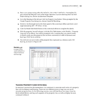
6. You will now see each vertex of the property line expressed as a distance and a NE
bearing, as shown in Figure 3.37.
Figure 3.37
a property line
can be defined in a
table of distances
and bearings.
Tagging property Lines with area
In standard construction documentation, it is customary to annotate each vertex of a property
line with its distance and bearing. There are two different types of tags you can use to
annotate property lines. In the following exercise, you will load these two types from the
Revit default library and tag each segment of the property line, as well as display the area
contained within it.
c03.indd 101 5/3/2014 10:31:08 AM